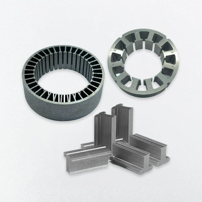
BLDC Motor Stator and Rotor
- Our BLDC motor stator and rotor feature high-speed lamination, low-loss materials, and precision winding for optimal efficiency.
- With full customization in diameter, lamination thickness, and magnet layout, we deliver reliable, high-performance solutions tailored to your exact motor core design requirements.
- Custom laminations tailored to provided drawings
- Adjustable stack length, tooth width, slot shape
- Versatile Stator and Rotor Types
- Prototyping and small-batch production available
How Do the Stator and Rotor Work with Each Other in A BLDC Motor?
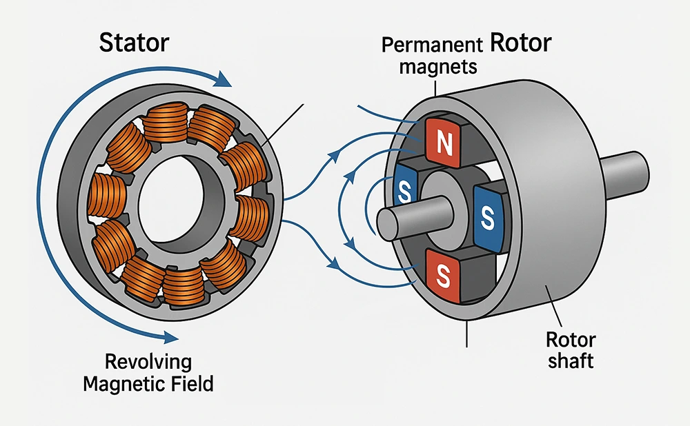
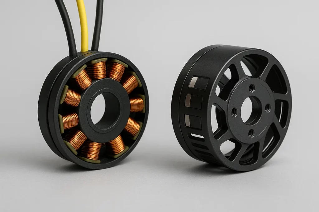
In a BLDC motor, the stator and rotor interact through electromagnetic fields to generate torque.
- The stator consists of copper windings wound around laminated steel cores. It produces a revolving magnetic field when powered.
- The rotor contains permanent magnets that follow this field, turning the rotor shaft.
- BLDC motors use electronic switching to energize stator phases in sequence. The rotor is driven by the revolving magnetic field that it produces. As the field changes, the rotor aligns with it, turning electrical energy into mechanical motion.
- Precise design and magnetic balance of both parts are crucial. Misalignment, poor winding, or magnet issues can affect speed control, efficiency, and heat stability.
BLDC Motor Stator Types
The slot wound, coreless, segmented, and hairpin designs of our BLDC motor stators are designed for accuracy, effectiveness, and heat management.
Slot Wound Stator
- Copper wire in slots ensures magnetic coupling and torque.
- Lamination 0.2–0.5mm supports heat dissipation and high-speed use.
- Custom diameter 20–300mm, stable operation up to 60,000 RPM.
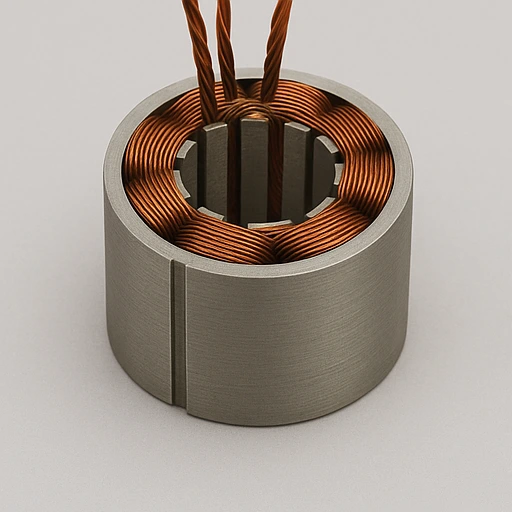
Coreless (Slotless) Stator
- Air-core design eliminates cogging, ensures smooth, quiet rotation.
- Copper wire 0.05–0.3mm wound on non-magnetic base.
- Lightweight, low inductance improves response and efficiency.
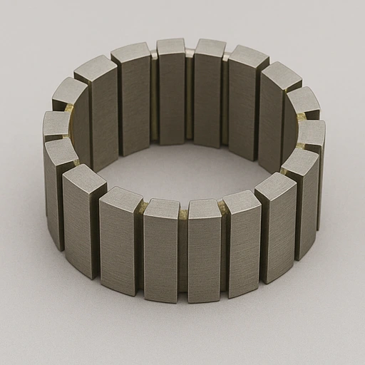
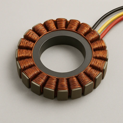
Segmented Stator
- Made of insulated segments to reduce losses and ease assembly.
- Arc angle 10°–30°, allows modular, precise winding setup.
- Enhances cooling, supports repairs, custom tooth width and height.
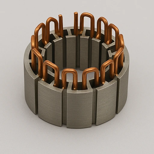
Hairpin Wound Stator
- Rigid copper hairpins inserted and laser welded for accuracy.
- High slot fill supports voltage endurance and heat transfer.
- Lamination 0.3mm, diameter 80–300mm, fits automated lines.
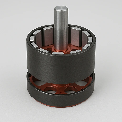
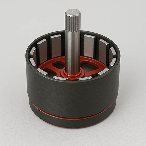
BLDC Motor Rotor Types
The inner, outer, SPM, and IPM designs of our BLDC motor rotors are all designed for particular torque, speed, and magnetic performance.
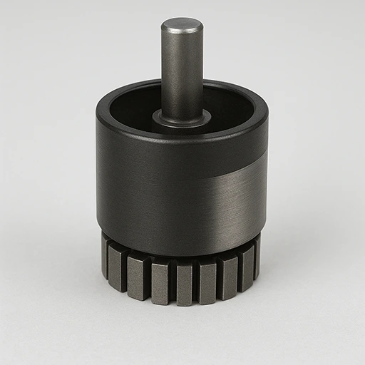
Inner Rotor
- Rotor inside stator for better cooling and high-speed rotation.
- Shaft diameter 10–80mm with 0.2–0.5mm lamination.
- Low inertia improves torque density and fast dynamic response.
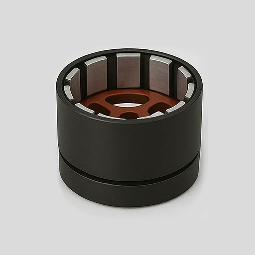
Outer Rotor
- Rotor wraps stator for smooth, stable, low-speed performance.
- Outer diameter 60–130mm, lamination 0.3–0.5mm.
- Higher torque from larger air gap and rotor mass.
Surface-Mounted Permanent Magnet (SPM) Rotor
- Magnets fixed on rotor with strong adhesive or sleeve.
- NdFeB or ferrite magnets reduce cogging, increase torque.
- Diameter 20–100mm, magnet thickness about 2–5mm.
Interior Permanent Magnet (IPM) Rotor
- Embedded magnets produce saliency torque and better efficiency.
- Lamination 0.2–0.35mm, diameter 30–120mm.
- Ideal for high-speed, field-weakening torque demands.
Our Precision Manufacturing Process
- Each BLDC motor stator and rotor is crafted through precision engineering, automated production, and strict multi-stage quality inspection standards.
- Mold Design & Engineering: Create precision stamping die designs based on validated prototype data and required lamination tolerances.
- Core Stamping: High-speed presses create accurate laminations with minimal deformation and burrs.
- Stacking & Bonding: Laminations stacked and bonded to ensure strength and magnetic uniformity.
- Winding Process: Automated winding ensures precise coil distribution and insulation integrity.
- Impregnation & Curing: Epoxy applied and heat-cured for insulation and thermal stability.
- CNC Machining: Achieve micron-level precision on shaft holes and end surfaces.
- Magnet Installation: High-grade magnets positioned for balanced torque and smooth operation.
- Dynamic Balancing: Rotors finely balanced to minimize vibration and noise during use.
- Quality Testing: Comprehensive electrical and mechanical tests ensure superior performance.
Customer Case
A drone company in Nagoya, Japan sought a lightweight, efficient stator-rotor set for precision spraying in their new agricultural drone series.
Customer Requirements
- Lightweight core reduces overall drone weight
- Operates steadily at 10,000–15,000 RPM
- Low cogging torque ensures smooth, precise motion
- Stator diameter limited to 65 mm
- High thermal conductivity supports long use in heat
- Resists corrosion from pesticides and humidity
- We created a coreless stator using a non-magnetic resin base and 0.06 mm copper wire to reduce weight and cogging torque, with epoxy insulation for durability.
- The rotor adopted an outer design with surface-mounted NdFeB magnets and an anodized aluminum body for enhanced torque, speed, and corrosion resistance.
- Cooling vents, automated concentricity checks, and inline resistance testing ensured thermal stability and consistent production quality.
Results
| Parameter | Customer Requirement | Delivered Result |
| Stator Outer Diameter | ≤ 65 mm | 64.2 mm |
| Motor Speed | 10,000–15,000 RPM | Stable at 15,300 RPM |
| Cogging Torque | Near zero | < 0.2% of peak torque |
| Weight (Stator + Rotor) | ≤ 180 g | 162 g |
| Thermal Performance | Operate in 40°C+ ambient | Stable at 45°C continuous |
| Corrosion Resistance | Required | Epoxy + anodized protection |

