Robotics is growing fast and needs more precise, efficient motion control. Stepper motors help, but standard types often fall short. Custom stators and rotors are now crucial for meeting specific robotic needs.
Why Custom Stepper Motors Matter in Robotics
The Limitations of Standard Stepper Motors
Standard stepper motors resemble the “one-size-fits-many” approach in electromechanical design. Available in discrete sizes (e.g., NEMA 17, 23, 34), fixed winding configurations, and typical step angles (1.8°, 0.72°), they cater well to general-purpose motion control. However, robotics presents a host of nuanced challenges:
- Compactness with High Torque: Robotics subassemblies—like articulated arms, grippers, or camera gimbals—require motors that are physically small yet capable of delivering high torque. Off-the-shelf solutions often trade off one for the other.
- Low-Ripple Torque: Smooth motion without micro-vibration is critical for applications like microscopic manipulation or optical stages. Custom pole designs can minimize detent torque and torque ripple.
- Foreign Environment Tolerance: Robotics often ventures into extremes—whether high-vibration industrial environments, sterilizable medical settings, or temperature extremes. Standard motors may need redesigning of stator coatings, rotor magnets, and bearing assemblies to cope.
- Multi-Phase Configurations: Certain high-performance tasks benefit from more than the standard two or three phases, enabling finer control, smoother motion, and redundancy.
Custom Solutions: Driving Performance Gains
Tailored stepper motor stator and rotor assemblies unlock significant gains:
- Optimized Electromagnetic Topology: By adjusting pole counts, skew angles, winding patterns, and slot geometry, engineers achieve precise torque-per-winding, torque ripple characteristics, and efficiency tailored to the robotic system.
- Motor Miniaturization: Advanced rotor-stator designs (such as thin-profile laminated iron cores or bonded alloys) permit high torque densities in smaller envelopes.
- Environmental Customization: Custom coatings like conformal stator varnish, epoxy encapsulation, and rotor magnet anti-corrosion plating enable alchemical-level tolerance to moisture, dust, heat, or chemicals.
- Integrated Sensing Solutions: Incorporating Hall-effect sensors, magnetic encoders, or temperature sensors directly into the stator or rotor assemblies enables seamless system integration and advanced feedback control.
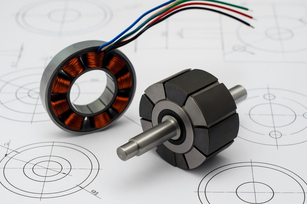
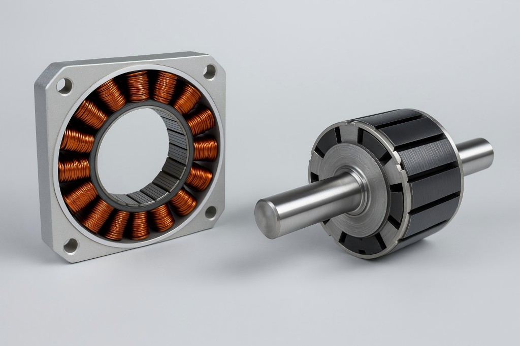
Key Design Elements of Custom Stators and Rotors
Stator Architecture and Winding Schemes
The stator is the stationary powerhouse: a laminated iron core with coils wound to produce rotating magnetic fields. Custom design considerations primarily involve:
- Lamination Panel Design: Engineers select slot/pole combinations to control step angle (e.g., move from 1.8° to 0.45° by changing pole count). Skewed laminations reduce torque ripple but raise manufacturing complexity. Specialized lamination profiles also allow interior stators for hollow-shaft designs or compact frame profiles.
- Winding Topology: Standard series or parallel bipolar windings may give way to multi-layer or overlapped winding architectures. Fine gage magnet wire (e.g., 28–32 AWG) with epoxy resin fill aids miniaturization, enabling multiple turns while maintaining thermal performance.
- Insulation and Thermal Management: Custom insulations—Class H or C varnishes—enhance temperature tolerance. Some stators integrate conductive cooling paths or vapor-channel circuits to actively dissipate heat in high-power applications.
- Sensor Integration: Embedding Hall sensors at precise angular positions within the stator core enables closed-loop control without external mounts. Magnetic encoders can also be included for sub-microstep control.
Rotor Configurations
The rotor, housing the permanent magnets or variable reluctance poles, must complement the stator design to deliver precise, torque-optimized motion. Considerations include:
- Magnet Quality: Rare-earth magnets (typically N45–N52 NdFeB) offer high energy density in miniature packages. Custom magnets may be segmented, skewed, or bonded in special configurations to control flux distribution and reduce cogging torque.
- Rotor Core Design: Laminated interior rotors support low inertia and efficient flux paths, while heavy iron slotted rotors improve inertial stability in high-load scenarios. Hybrid designs combine both for targeted use cases.
- Thermal Behavior: Rotor magnet performance degrades at high temperatures. Custom radially ventilated rotors, enhanced coatings, or internal thermistors can mitigate this effect.
- Mechanical Features: When stability is critical—e.g., surgical robotics or micro-exploration drones—rotor dynamic balancing becomes a requirement. Custom counterweight features and mating shaft designs are engineered to meet tight vibration specifications (sub-10 µm residual imbalance).
Manufacturing Techniques and Innovations
Advanced Stamping and Lamination
Precision stamping of laminations is the most common route for stator cores. Custom profiles and special slit laminations enable skew angles as low as 1° per pole to reduce torque ripple. Edge quality is controlled to < 5 µm dimensional tolerance, minimizing air-gap eccentricity. Alternative bonded cores—produced via adhesive lamination—enable complex core shapes, such as with interior bore splines for hollow shafts.
High-Precision Winding
Automated micro-winding platforms—built specifically for size-defying stators—allow 32 AWG or finer wire to be wound in cross-over or multi-layer patterns with < 1 N advance tension control. Resin transfer molding (RTM) or vacuum resin impregnation yields void-free winding packs that endure thermal cycles and mechanical shock.
Magnet Handling and Assembly
Rotor magnet assembly is carried out in ISO 14644-class cleanrooms, using automated pick-and-place tools to accurately orient each magnet segment. Adhesives certified for high temperature and mechanical stress (e.g., 200 °C epoxy) are used to ensure rotor integrity. Subsequent balancing—static and dynamic—is performed to ISO 1940 A1.5 standards or better.
Coating and Overmolding
For harsh environments, stators are coated with conformal layers of varnish or epoxy resin, 0.5 mm thick. Rotors may be nickel-plated or powder-coated for corrosion resistance. In submarine, chemical-exposed, or vacuum applications, fully overmolded motors using TPU encapsulation provide complete environmental isolation.
Control Electronics and Integration
Custom rotor-stator designs are only half the story; they must be paired with electronics that can exploit their capabilities:
Driver and Amplifier Matching
High-performance stepper motors may require current-mode bipolar drivers capable of microstepping to 256 or 512 steps/rev. In high-voltage scenarios, linear drivers are favored for smooth current regulation at frequencies up to 100 kHz. Some systems integrate the driver circuitry directly onto the motor housing—minimizing wiring and EMI while enabling advanced current feedback loops.
Feedback Mechanisms
Integrating Hall sensors or encoders within the stator enables closed-loop control, turning a stepper motor into a servo hybrid. This results in the ability to detect missed steps, maintain position under load, and eliminate resonance. Custom firmware and control algorithms—such as LQG or H∞—optimize performance, adaptive current tuning, and anti-resonance strategies.
Communication and Connectivity
In distributed robotic systems, motors are connected via industrial fieldbuses (EtherCAT, CANopen, SERCOS) or wireless protocols (e.g., Wi-Fi 6, BLE 5.2). Custom motor electronics support resilience features like cyclic redundancy checks, hot-swap capability, and in-situ diagnostics. Maintenance shift left—firmware updates and run-time trace logs enable predictive maintenance across OEM fleets.
Application Case Studies
To illustrate the impact of custom stator-rotor engineering, here are several real-world deployments across robotics verticals.
Precision Medical Robotics – Micro-Surgical Manipulator
A medical robotics firm developing tools for ophthalmic surgery encountered limitations with standard NEMA 8 motors—they were too coarse and thermally unstable in body-temperature environments (37 °C). The company partnered with a mechatronics vendor to develop:
- A 48-pole stator laminated with skewed teeth at 0.8° per pole for ultra-low torque ripple
- Embedded thermistor and micro-encoder within the stator bore
- A rotor with ultra-thin bonded NdFeB magnets, high thermal stability, and < 2 µm dynamic balancing
- Cryogenically rated varnish coatings
Resulting performance: microstep resolution of 0.0075°, zero detectable jitter down to 0.5 µm of translation, and thermal runaway containment during 60-minute continuous operation.
Industrial Robotics – High-Speed Pick & Place
An electronics assembly facility required sub-5 ms step transitions and precision placement at 45 k picks per hour with minimal downtime. A custom motor was developed featuring:
- A six-phase stator enabling fine microstepping
- Interior-vented rotor optimized for forced-air cool-down
- Surface-machined detent compensation via skewed poles
This enabled closed-loop operation at 200 kHz PWM frequency, delivering 0.12° stepping resolution, energy recovery on deceleration, and cumulative downtime reduction of 3.6 hours per month per line.
Space Robotics – Lunar Rover Actuation
A space robotics contractor designing exploratory rover joints bound for the lunar surface (temperature swings of –180 °C to +120 °C), required motors that could survive thermal shock and vacuum outgassing. The resulting custom solution featured:
- An interior stator using vacuum-compatible bonded laminations and kapton-insulated windings
- Epoxy-potted rotor with radiation-hardened rare-earth magnets and Cerakote terrestrial coating
- Dual-redundant Hall sensors rated to ISO 6070 radiation levels
- Fully balanced rotor (< 0.1 g·mm residual imbalance)
These motors passed a combined thermal-vacuum cycling test (Mil-Std-810) and demonstrated ≥2 million cycles of operation at ±5°C/s ramp rates without performance degradation.
Business Considerations and Market Trends
Cost vs. Performance Trade-Off
Custom stator‑rotor motors can cost 2–5× more than standard off‑the‑shelf variants, driven by tooling, materials, precision manufacturing, and testing requirements. However, when performance gains enable higher throughput, reduced assembly downtime, or new business opportunities (e.g., in medical or space), ROI becomes compelling.
Supply Chain and Lead Times
Custom lamination tooling, winding machines, and magnet machining require lead times of 8–16 weeks. Strategic inventory planning or modular platform strategies—pairing standard stator stocks with custom windings or rotors—helps manufacturers mitigate long lead times and inventory costs.
Regulatory and Standards Compliance
Medical robotics mandates IEC 60601, space missions rely on NASA/ESA standards (e.g., ECSS), and industrial lines align to ISO 9001 and UL ratings. Custom motors may demand UL‑recognized components, biocompatible materials, or low-outgassing adhesives. Quality systems must be accredited and traceable from design to shipping.
Emerging Trends
Additive Manufacturing: Metal 3D‑printed stator cores enable topology-optimized flux paths with integrated cooling channels—though currently bottlenecked by cost and post-annealing needs.
- Rare-Earth Magnet Alternatives: As NdFeB prices fluctuate, some vendors are trialing bonded ferrite or AlNiCo backups—trading off torque density but offering thermal resilience.
- Smart Motors: Motors embedding IoT-ready microcontrollers and predictive health analytics over real-time network protocols help OEMs shift from warranty models to performance-as-a-service.
Engineering Workflow for Custom Motor Development
Step 1: Requirements Capture
Motors begin as conversation: what’s the performance envelope, environmental constraints, physical envelope, and end-of-life? Key variables include torque curves, step resolution, volume/weight constraints, temperature/humidity/exposure factors, lifecycle cycles, noise, and regulatory standards.
Step 2: Electromagnetic Design
Solaris or Flux may be used to iterate lamination patterns, slot/pole counts, skew, and winding layout. Engineers simulate torque vs. speed, holding torque, torque ripple, core losses, and flux saturation levels.
Step 3: Mechanical/Structural Design
Integration of rotor balancing, housing interface, thermal dissipation paths, and mechanical shielding is modeled in SOLIDWORKS or CATIA. Fastener preloads, axial runout, bearing selection, and radial stiffness are analyzed.
Step 4: Prototype and Test
A small batch prototype (typically 5–10 units) is made and subjected to engineering tests: flux measurement, ID gearbox interface checks, thermal cycling, static/dynamic balancing, and vibration & acoustic noise spectrum. When needed, compliance tests (medical leak testing, vacuum bake-out, EMI/EMC) are performed.
Step 5: Iteration and Production
Performance deficiencies feed back into the design loop—e.g., skew adjustment, winding fill changes, or coating modifications. Once validated, production tooling is finalized, supply chain locked, and ongoing quality control measures (Cp/Cpk tracking, torque curve batch controls) are implemented.
Challenges and Opportunities
Challenges
- Complexity vs. Reliability: More customized solutions introduce more variables—skewed laminations, fine winding packs—that demand strict manufacturing control.
- Scale-up Costs: With smaller volumes (hundreds to a few thousand), tooling amortization becomes significant.
- Material Dependencies: Fluctuating costs of iron alloys and rare-earth materials impact pricing and design decisions.
- Supply Chain Resilience: For materials like NdFeB magnets or Class H varnish, sourcing redundancy is critical to avoid delays.
Opportunities
The very complexity that poses challenges also opens innovation frontiers:
- High-Performance Niche Markets: Medical robots, surgical devices, aerospace, micro assembly machines, and space robotics operate in performance spaces where return per motor far outweighs per-unit costs.
- Modular Custom Platforms: OEMs can select from scalable family platforms—standard core dimension with customizable skew, winding, magnets—lowering overall cost while delivering modular performance.
- Smart Motor Servicing: Embedded diagnostics, network connectivity, and performance data create opportunities for subscription companies to offer motor-as-a-service or condition-based maintenance.

