Electric motors power many modern technologies, from electric vehicles to household appliances and industrial machines. At their core are two key parts: the stator and the rotor.
These components work together to turn electrical energy into motion, or the other way around. Though they function as a pair, the stator and rotor differ in how they’re built, the materials they use, how they handle heat, and their roles in producing motion.
This article explains these differences and looks at how their designs continue to improve with new technology.
Introduction to Electric Motors and Their Core Components
Electric motors are energy-conversion devices that use electromagnetic interactions to convert electrical energy into mechanical work. Generators operate in reverse, converting mechanical energy into electrical output. Two parts are at the heart of both machines:
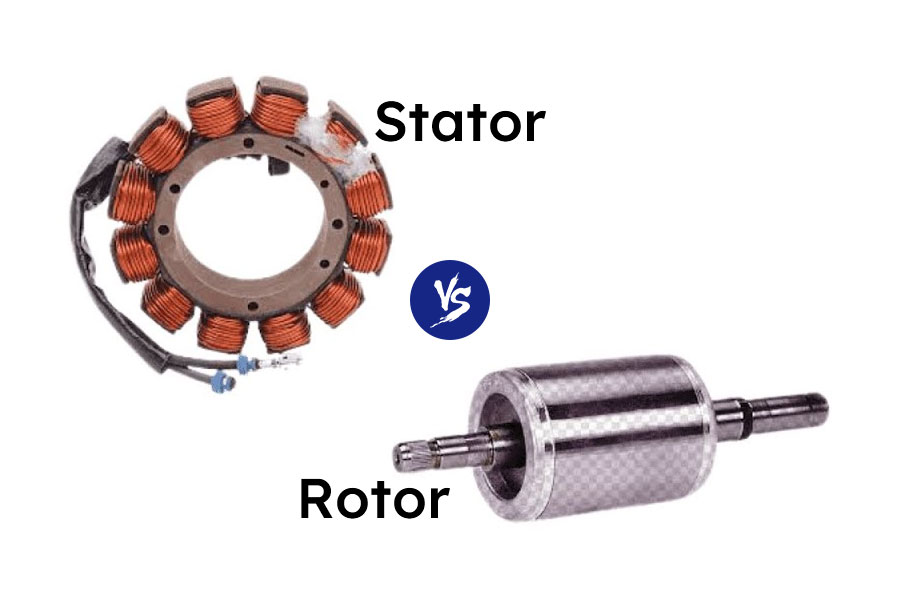
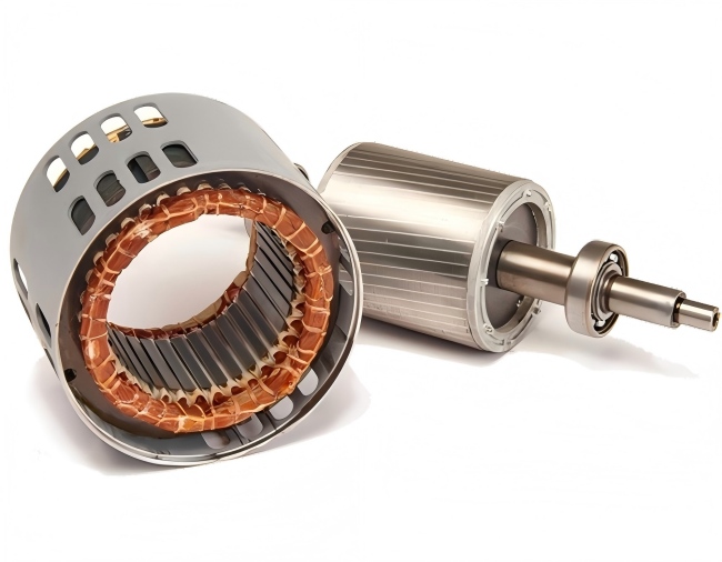
- Stator: The component that creates a magnetic field that is stationary.
- Rotor: The component that revolves when subjected to a magnetic field.
Understanding their symbiotic relationship is crucial for engineers, manufacturers, and researchers optimizing performance across sectors.

Basic Definitions and Functional Roles
What is a Stator?
The stator is an electric motor or generator stationary component. It typically consists of windings or permanent magnets and acts as the primary source of the magnetic field in most machines. The stator is responsible for setting up a rotating magnetic field (in AC motors) or providing a fixed magnetic field (in some DC or BLDC motors).
What is a Rotor?
The rotating component inside the stator, situated on a shaft, is called the rotor. To create torque, it interacts with the stator’s magnetic field. In a generator, the rotor is turned mechanically, inducing voltage in the stator windings.
Together, They Enable Motion
While the stator sets the conditions for electromagnetic induction, the rotor is what responds to it, creating actual motion. Their interaction forms the core of electromechanical energy conversion.
Structural Comparison
| Feature | Stator | Rotor |
| Motion | Stationary | Rotating |
| Location | Outer part of the motor | Inner part, mounted on a shaft |
| Magnetic Role | Creates the magnetic field | Engages in field interaction to generate motion. |
| Components | Laminated core, windings, insulation | Laminated core, conductors or permanent magnets |
| Housing | Fixed to the motor casing | Connected to the rotating shaft |
The stator is typically larger in size and mass due to its housing, insulation, and sometimes cooling components. The rotor, being mobile, is more compact and engineered for low inertia.
Material Composition and Manufacturing Differences
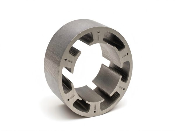
Stator Materials
- Laminated Silicon Steel: Reduces eddy current losses.
- Copper or Aluminum Windings: For efficient current carrying.
- Insulation Paper, Varnish, Epoxy: For electrical and thermal protection.
- Iron Core: To guide magnetic flux.
Rotor Materials
- Conducting Bars (Aluminum/Copper): For squirrel cage induction motors.
- Permanent Magnets: In PMDC and BLDC motors.
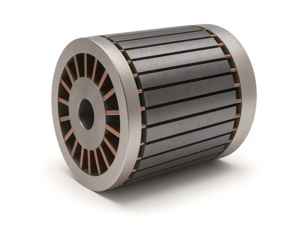
- Laminated Core: Similar to stator but optimized for mechanical strength.
Manufacturing Techniques
- Stator: Requires complex winding (round or hairpin), insulation layering, and often thermal treatment.
- Rotor: May involve die-casting (e.g., aluminum bars in squirrel cage), magnet insertion, balancing, and shaft assembly.
Electromagnetic Principles at Work
At the heart of the stator and rotor interaction are the Lorentz force law and Faraday’s law of electromagnetic induction.
- The stator in AC motors creates a rotating magnetic field. Torque is produced by the rotor conductors creating their own magnetic field to counteract the change after this spinning field induces a current in them (induction).
- In DC motors, the stator provides a steady magnetic field while the rotor (with a commutator) switches polarity to maintain motion.
- In BLDC motors, electronic controllers switch the stator current to produce a rotating field that pulls the permanent magnet rotor along.
Types of Motors and Their Stator-Rotor Variants
Induction Motors (Asynchronous)
- Stator: Three-phase windings to generate rotating field.
- Rotor: Usually squirrel-cage type, no direct power supply.
Synchronous Motors
- Stator: Produces rotating magnetic field.
- Rotor: Rotates at same speed as field; may use permanent magnets or DC field windings.
Brushless DC Motors (BLDC)
- Stator: Electronically commutated windings.
- Rotor: Permanent magnets—inner or outer rotor variants.
Stepper Motors
- Stator: Several poles of an electromagnet.
- Rotor: A device that resembles a gear and can be either variable reluctance or permanent magnet.
Switched Reluctance Motors
- Stator: Energized sequentially to pull rotor teeth.
- Rotor: Salient pole rotor, no windings or magnets.
Key Performance Roles
| Parameter | Stator Contribution | Rotor Contribution |
| Magnetic Field Strength | Generates primary field via windings | Reacts to field; may generate secondary field |
| Torque Generation | Induces field and flux alignment | Converts magnetic interaction to motion |
| Efficiency | Affects flux quality and losses | Affects rotational inertia and losses |
| Heat Dissipation | Houses main losses (I²R, core losses) | Lower losses, but heat must be managed |
| Maintenance | More complex due to wiring | Bearings, shaft wear more likely |
Common Failures and Maintenance Considerations
Stator Failures
- Insulation Breakdown: Overheating, voltage surges, or age.
- Shorted Windings: Leads to uneven torque or total motor failure.
- Vibration Cracks: In laminations or mounts.
Rotor Failures
- Rotor Bar Breakage: Common in squirrel cage motors.
- Imbalance: Caused by manufacturing defects or wear.
- Shaft Misalignment: Leads to bearing wear or stator contact.
Predictive maintenance techniques like thermal imaging and vibration analysis often target rotor issues, while insulation testing and surge testing focus on stator health.
Cooling Mechanisms and Thermal Roles
Stators handle the majority of heat dissipation because of current in windings. As such:
Stator cooling methods:
- Air-cooled with fins or forced fans
- Liquid-cooled via embedded channels
- Use of thermally conductive epoxy
Rotor cooling methods:
- Limited options due to rotation
- Internal ducts and centrifugal air flow in large motors
- Thermal conductivity via shaft to external heat sinks
Efficient stator cooling increases motor lifespan and operational stability, particularly in high-torque or continuous-duty applications.
Stator and Rotor in Generators
In electric generators, the functional roles of stator and rotor reverse, though the construction remains similar.
- Rotating Field Generator: Rotor acts as an electromagnet (fed by slip rings or PMs), inducing voltage in stationary stator windings.
- Stationary Field Generator: In rare designs, rotor contains windings and spins within a stator magnet.
This reversal still adheres to the laws of induction—relative motion between a conductor and a magnetic field is the key.
Advancements in Stator and Rotor Technologies
Lamination Improvements
- From 0.5mm to ultra-thin 0.2mm or 0.1mm electrical steels
- Coatings for insulation and corrosion resistance
High-Speed Rotor Balancing
- Dynamic balancing for turbo motors (up to 100,000 RPM)
- New alloys to reduce centrifugal deformation
Hairpin Winding for Stators
- Offers higher fill factor and better thermal conductivity
- Automated winding enhances consistency
Additive Manufacturing (3D Printing)
- Used for rapid rotor prototyping
- Lattice design stator cores with optimized flux paths
Rotor Embedding Technology
- V-shaped permanent magnets in rotors for better field control
- IPM (Interior Permanent Magnet) design improves torque density
Applications by Industry
| Industry | Stator Role | Rotor Role |
| Automotive | Precise torque control in EV motors | High-speed rotation in drive units |
| Aerospace | Lightweight winding for fuel pumps | Low-inertia rotors for actuation systems |
| Medical Devices | Quiet operation in imaging tools | Vibration-free rotor design |
| Robotics | Precise positioning via stator feedback | Dynamic balancing for agile movement |
| Renewable Energy | Large stators in wind turbine generators | Rotor blades convert wind to rotation |
Rotor vs. Stator: Summary of Key Differences
| Category | Stator | Rotor |
| Position | Fixed part | Rotating part |
| Function | Generates magnetic field | Converts magnetic interaction to torque |
| Construction | Windings, laminations, insulation | Laminations, conductors or magnets |
| Cooling | Easier due to stationary position | More difficult due to rotation |
| Maintenance | Electrical diagnostics needed | Mechanical diagnostics needed |
Designing for Performance: Stator and Rotor Optimization
Engineers optimize the stator and rotor differently based on the application:
- For High Torque: Increase stator winding turns, use high-grade lamination steel, use strong permanent magnets in the rotor.
- For High Speed: Design low-inertia rotors, tight rotor balancing, and smooth stator slot shapes.
- For Efficiency: Use hairpin winding, minimize air gap, and reduce eddy current loss via thin laminations.
Finite Element Analysis (FEA) is frequently used by designers to optimize the interaction between the stator and rotor and model electromagnetic fields.
Future Trends
- Solid-State Cooling: Emerging thermal solutions using phase-change materials in stator.
- Sensorless Control: Using rotor position algorithms to eliminate mechanical encoders.
- Smart Materials: Shape-memory alloys in stator supports and self-healing insulation.
- Modular Motor Architecture: Swappable stator-rotor kits for field servicing.
With AI-driven control systems and new materials, the stator and rotor will continue to evolve in synergy for smarter, lighter, and more efficient motors.
Conclusion
The stator and rotor work together but are quite different in how they’re built and what they do. When the rotor rotates, the energy is converted into motion, while the stator remains motionless and generates a magnetic field. Together, they drive most electric machines we use today.
Understanding how they work—right down to their materials and energy losses—is key for engineers and anyone looking to improve electric motor technology in today’s fast-changing world.

