
Electricity powers modern civilization—from lighting homes and driving industries to enabling digital infrastructure and transportation. At the core of every power plant, whether it’s a massive hydroelectric dam, a wind turbine, or a compact diesel generator, lies one essential device: the electric generator.
Central to this process are two indispensable components: the stator and the rotor. Together, they form the dynamic heart of power generation, transforming motion into usable electric current.
The Principle of Electromagnetic Induction
To understand the generator stator and rotor, we must first recall Faraday’s Law of Electromagnetic Induction, which states that a voltage is induced in a conductor when it experiences a change in magnetic flux. In a generator, this is achieved by the relative motion between magnetic fields and conductors.
- The rotor produces or carries the magnetic field and rotates inside the machine.
- The stator holds the conductors (coils) where electricity is induced.
When the rotor spins, its magnetic field sweeps across the stationary windings of the stator, generating alternating current (AC) or direct current (DC), depending on the generator’s design. This simple yet powerful interaction is the basis for nearly all modern electricity production.
Anatomy of a Generator
A typical generator consists of several key parts working together:
- Stator: The stationary part that contains the windings where voltage is induced.
- Rotor: The rotating part that produces a magnetic field.
- Shaft: Connects the prime mover (e.g., turbine, engine) to the rotor.
- Bearings: Support the rotor and allow smooth rotation.
- Housing or Frame: Provides structural integrity and cooling pathways.
- Excitation System: Supplies DC current to the rotor windings in synchronous machines.
Among these, the stator and rotor perform the core electromechanical energy conversion, determining the generator’s voltage, frequency, and efficiency.
Generator Stator
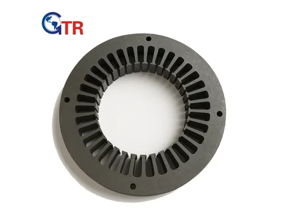
The stator forms the outer stationary portion of the generator and is designed to withstand mechanical stress, magnetic forces, and heat. It typically consists of three main parts:
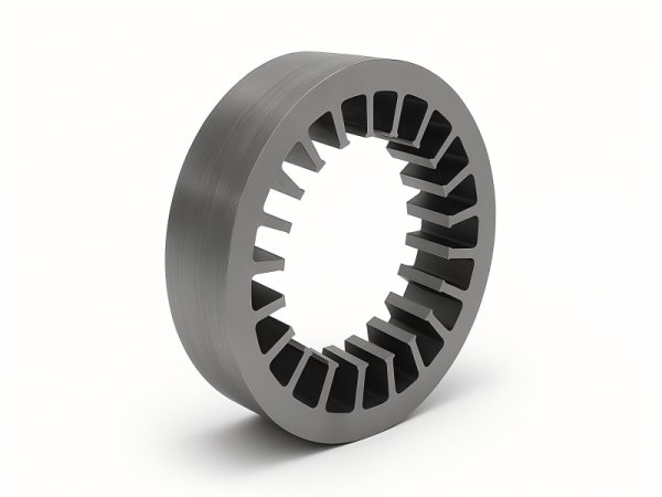
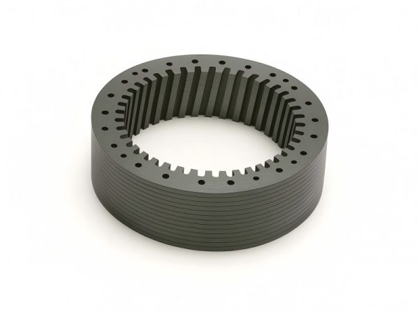
Stator Core
The stator core is made from laminated silicon steel sheets stacked together to reduce eddy current losses. These laminations are insulated from each other and carefully assembled within the generator frame. The purpose of the core is to provide a low-reluctance path for the magnetic flux while minimizing energy losses.
Stator Windings
Copper or aluminum windings are inserted into slots in the stator core. These coils are connected in a specific configuration—usually star (Y) or delta (Δ)—depending on voltage and current requirements. As the rotor’s magnetic field rotates, it cuts through these coils, inducing alternating voltage.
Stator Frame and Cooling
The stator frame provides mechanical support and helps dissipate heat. Modern generators use advanced cooling techniques such as air, hydrogen, or water cooling to maintain optimal operating temperatures. In large power generators, hydrogen cooling is especially popular due to its superior heat transfer and low friction losses.
Insulation and Protection
Insulation materials are critical to prevent electrical breakdown. Mica-based or epoxy-resin systems are often used, and the insulation must endure mechanical vibration, thermal expansion, and electrical stress throughout the machine’s life.
Generator Rotor
The rotor is the heart of motion—it carries the magnetic field that interacts with the stator windings. Its design varies depending on the type of generator (synchronous or asynchronous).
Types of Rotors
Salient Pole Rotor:
- Common in hydroelectric generators and low-speed applications.
- Has projecting poles with concentrated field windings.
- Larger diameter and shorter axial length.
- Provides high magnetic flux but limited mechanical strength at high speeds.
Cylindrical (Non-salient) Rotor:
- Used in steam turbines and gas turbine generators, where high rotational speeds (3,000 rpm or more) are typical.
- Rotor surface is smooth, with slots for embedded field windings.
- Ensures mechanical balance and minimal windage loss.
Field Windings and Excitation
The rotor’s magnetic field is created through DC excitation, supplied either by brushes and slip rings or by a brushless excitation system. In brushless systems, a small AC generator (exciter) mounted on the same shaft produces current, which is rectified and fed into the rotor.
The strength of the magnetic field (controlled by excitation current) determines the output voltage of the generator. Advanced digital excitation systems allow precise control, improving voltage regulation and stability.
Mechanical Construction
Rotor shafts are forged from high-grade alloy steel, machined to balance precision, and heat-treated for strength. The field windings are embedded in slots and secured with retaining rings to withstand centrifugal forces during high-speed rotation.
Cooling Methods
Because the rotor operates in a high-temperature environment, cooling is vital. Large rotors use radial or axial air ducts for circulation. Some high-capacity machines employ direct hydrogen or water cooling, ensuring minimal temperature gradients and extending insulation life.

How the Stator and Rotor Work Together
The interaction between stator and rotor defines generator performance. In synchronous generators, the rotor’s magnetic field rotates at the same speed as the rotating magnetic field of the stator. This speed, known as synchronous speed (Ns), is determined by the formula:
Ns=120f/P
where f is the frequency (in Hz) and P is the number of poles.
For example, in a 4-pole generator operating at 60 Hz, the synchronous speed is 1,800 rpm.
As the rotor spins at this speed, its magnetic field cuts across the stator windings, inducing alternating voltage. The amplitude of this voltage depends on the strength of the magnetic field and the speed of rotation, while the frequency depends solely on rotor speed and pole count.
In induction generators, common in wind turbines, the rotor rotates slightly faster than the synchronous speed. This “slip” allows energy to flow from the mechanical system into the electrical grid without the need for separate excitation.
Materials and Manufacturing Precision
The performance and reliability of a generator depend heavily on the materials used in both stator and rotor construction.
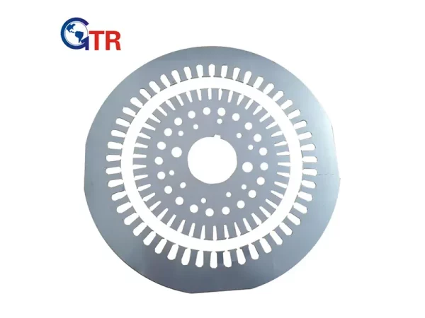
Magnetic Materials
Silicon steel laminations with low hysteresis loss are used to form stator and rotor cores. These materials ensure high magnetic permeability, minimizing energy losses during magnetization cycles.
Conductors
Copper is the preferred conductor material due to its high conductivity and thermal resistance. In large-scale machines, water-cooled copper bars or hollow conductors are used to manage heat effectively.
Insulation Systems
Insulation must withstand high voltage, vibration, and temperature cycling. Class F or H insulation systems, rated up to 155°C and 180°C respectively, are standard in modern generators.
Balancing and Testing
Rotor balancing is critical. Even minor asymmetry can cause vibration, bearing wear, and catastrophic failure. Therefore, rotors are dynamically balanced at both low and high speeds during manufacturing. High-voltage tests, partial discharge checks, and vibration analysis ensure long-term reliability.
Cooling and Ventilation Techniques
Heat is the natural byproduct of electrical and magnetic losses. Efficient cooling systems are crucial to maintaining generator longevity and performance.
Air Cooling
Used in smaller or medium-sized generators. Air is circulated by fans mounted on the rotor shaft.
Hydrogen Cooling
Hydrogen has excellent thermal conductivity and low density, reducing windage loss. It’s sealed within the generator casing and circulated through heat exchangers. This method is widely used in large turbine-driven units above 100 MVA.
Water Cooling
For extremely high-capacity generators, direct water cooling of stator windings or rotor conductors is employed. The water must be highly purified to prevent corrosion and electrical leakage.
Advanced Hybrid Systems
Some new-generation power plants adopt hybrid cooling methods combining air, hydrogen, and water for optimal heat removal while minimizing maintenance.
Efficiency and Losses
A generator’s overall efficiency depends on minimizing various losses:
- Copper losses: Caused by resistance in stator and rotor windings.
- Iron losses: Due to hysteresis and eddy currents in the magnetic core.
- Mechanical losses: Resulting from friction in bearings and air resistance.
- Stray losses: From leakage flux, harmonics, and circulating currents.
High-efficiency generators can exceed 98% performance by using advanced materials, precision manufacturing, and optimized cooling.
Modern Innovations in Stator and Rotor Design
Technological progress continues to enhance the design and functionality of stator and rotor assemblies:
High-Temperature Superconducting (HTS) Rotors
- Reduce electrical resistance almost to zero.
- Enable compact, lightweight machines with higher power density.
Smart Monitoring Systems
- Embedded temperature and vibration sensors track real-time health.
- Predictive maintenance reduces downtime.
Additive Manufacturing (3D Printing)
- Enables customized cooling channels and lightweight designs.
Advanced Magnetic Materials
Use of amorphous alloys or nanocrystalline steels to lower core losses.
Digital Twins
Virtual models simulate electromagnetic, thermal, and mechanical performance for optimization.
Common Faults and Maintenance Practices
Even with precision design, stators and rotors require regular maintenance to ensure safe and efficient operation.
Stator Faults
Winding short circuits due to insulation degradation.
Core hot spots from poor cooling or blocked ventilation.
Loose windings leading to vibration and mechanical wear.
Maintenance tips:
- Perform insulation resistance tests.
- Use thermal imaging for hot-spot detection.
- Keep air passages clean.
Rotor Faults
- Field winding open circuits or shorted turns.
- Rotor unbalance causing vibration.
- Bearing failure due to misalignment or contamination.
Maintenance tips:
- Monitor shaft vibration and bearing temperature.
- Conduct rotor pole drop and impedance tests.
- Balance the rotor dynamically during major overhauls.
Predictive Maintenance Tools
Modern plants use condition monitoring systems (CMS) integrating sensors for temperature, current, flux, and vibration to predict failures before they occur.
Applications Across Power Generation Technologies
The stator–rotor pair appears in all forms of generators, though adapted to different energy sources:
| Power Source | Generator Type | Rotor Type | Unique Feature |
| Hydroelectric | Synchronous | Salient Pole | Low-speed, high-torque |
| Steam Turbine | Synchronous | Cylindrical | High-speed, compact |
| Wind Turbine | Induction / Synchronous | Doubly-fed / PM | Variable-speed control |
| Diesel / Gas Engine | Alternator | Salient / Cylindrical | Portable, robust |
| Nuclear Plant | Turbo Generator | Cylindrical | Continuous duty, high output |
Regardless of size or energy source, the principle remains identical: the rotor’s magnetic field interacting with the stator’s windings to produce electricity.

