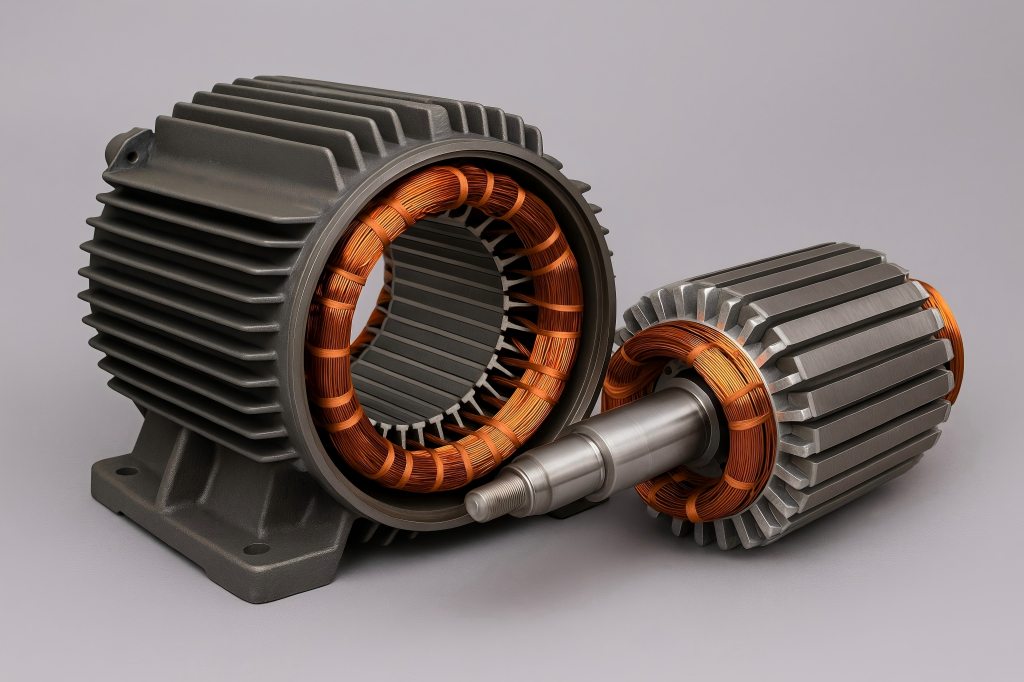
Modern industry’s workhorses are induction motors. But behind their reliability lies a complex and demanding fabrication process—especially when it comes to their core components: the stator and rotor. Manufacturers have to overcome a variety of technical obstacles to guarantee effectiveness, performance, and durability.
Material Selection
Proper material selection is the cornerstone of stator and rotor performance. These materials directly affect magnetic properties, thermal conductivity, electrical losses, and mechanical integrity.
Challenges
- Core Material Trade-Offs: Electrical steel laminations must balance low core loss with high magnetic permeability.
- Cost vs. Performance: High-quality non-oriented silicon steels (NOES) are expensive and susceptible to price fluctuations.
- Copper vs. Aluminum: Copper improves conductivity but increases cost and weight; aluminum is cheaper but less efficient.
- Supply Chain Variability: Inconsistent material quality can introduce variations in performance, particularly in large-volume runs.
Solutions
- Standardization: Choose materials with proven performance and documented standards (e.g., ASTM A683 or IEC 60404).
- Lamination Coatings: Use insulating coatings on laminations to minimize eddy currents and improve core efficiency.
- Material Testing: Implement material validation protocols—such as Epstein frame testing—for consistent performance.
- Hybrid Approaches: Use copper rotors in premium efficiency motors and aluminum in cost-sensitive applications to balance trade-offs.
Precision in Lamination and Stacking
Thin steel laminations are stacked to create the stator and rotor cores. Core loss, vibration, and noise are all affected by the precision of these laminations.
Challenges
- Burr Formation: During punching or laser cutting, burrs can create short-circuit paths between laminations.
- Inaccurate Stacking: Misaligned laminations create unwanted air gaps that disturb the magnetic flux path.
- Insulation Failure: Laminations lacking adequate surface insulation lead to increased eddy current losses.
- Core Vibration: Uneven stacking or inconsistent pressing causes magnetic imbalance and structural resonance.
Solutions
- Progressive Dies: Use tungsten carbide progressive dies for high-volume punching with minimal burrs.
- Laser Cutting for Prototypes: Adopt laser cutting for low-volume or prototype runs to reduce tooling costs and improve accuracy.
- Interlocking Stacking: Apply interlock or bonding techniques that ensure proper alignment and eliminate movement during operation.
- Vacuum Annealing: Use annealing to restore magnetic properties lost during cutting and reduce internal stress.
Automated stacking machines can dramatically reduce alignment errors, while modern camera-guided systems ensure layer uniformity.
Stator Winding Accuracy
Winding is the heart of the stator’s electromagnetic field generation. Poor coil placement or insulation can lead to hotspots, magnetic imbalance, and premature motor failure.
Challenges
- Manual Winding Errors: Irregular coil placement or over-tensioned wires can damage insulation and degrade winding quality.
- Insulation Breakdown: High-temperature environments cause early breakdown in low-grade insulations.
- Winding Shifts: Improper securing of coils results in movement during operation, causing electrical faults.
- Complex Geometries: Flat wire (hairpin) and multi-layer windings require specialized tooling and high repeatability.
Solutions
- Automated Winding Machines: Use programmable winding machines with tension control, robotic arms, and integrated monitoring.
- High-Temperature Materials: Select insulation materials like Nomex, Kapton, or mica-based wraps for demanding conditions.
- VPI (Vacuum Pressure Impregnation): This enhances coil bonding, improves thermal conductivity, and provides dielectric strength.
- Preformed Coils: In high-speed production, preformed and laced coils can maintain shape and positioning consistency.
Routine checks such as surge testing, hipot testing, and partial discharge analysis can prevent failures caused by weak insulation.
Rotor Casting Defects
The rotor cage (especially in squirrel cage motors) is typically die-cast with aluminum or copper. A well-formed cage is critical for maintaining torque output and rotational balance.
Challenges
- Incomplete Fill: Fast cooling or improper gating causes unfilled rotor bars, reducing conductivity.
- Porosity and Shrinkage: Impurities and shrinkage cavities impact mechanical integrity and thermal stability.
- Bar Misalignment: Poor mold alignment or shaft shifting leads to cage eccentricity, vibration, and uneven torque.
- Oxidation in Copper: Copper casting is prone to oxide inclusion at high temperatures, impacting performance.
Solutions
- Optimized Die Design: Use gated die-casting designs to ensure even flow and minimal turbulence.
- Vacuum Casting for Copper: Implement vacuum environments to prevent oxidation and porosity in copper rotors.
- Mold Preheating: Preheat dies to maintain fluidity and improve mold fill quality.
- Post-Casting Machining and Testing: Balance rotors dynamically, use X-ray and ultrasonic testing to detect internal flaws.
Copper die-cast rotors, while harder to fabricate, offer up to 20% lower losses and are preferred for IE3/IE4 premium efficiency motors.
Tight Tolerances in Machining and Assembly
The air gap between the stator and rotor—often just 0.2 to 1.0 mm—is crucial for efficient operation. Inaccuracies during machining or assembly can lead to friction, losses, or catastrophic failure.
Challenges
- Dimensional Inconsistencies: Shaft misalignment, improper bore sizing, and thermal deformation affect radial symmetry.
- Surface Defects: Poor surface finishes increase friction, noise, and wear over time.
- Stack Runout: Uneven rotor or stator stack surfaces affect rotor spinning dynamics.
- Thermal Expansion Mismatch: Aluminum and steel expand differently, leading to interference at high operating temperatures.
Solutions
- High-Precision CNC Machines: Use multi-axis CNC machining for stator bores and rotor shafts to achieve micron-level accuracy.
- Thermal Modeling: Predict thermal expansion during motor operation and adjust fits accordingly.
- Coordinate Measuring Machines (CMMs): Inspect parts with CMMs to verify tolerance conformity post-machining.
- Dynamic Balancing: Balance rotors at operating speeds to prevent vibration-related fatigue.
Tighter tolerances not only improve motor performance but also reduce noise and increase service life, especially in demanding HVAC and EV applications.
Bonus Challenge
Even when every individual process is optimized, ensuring consistent quality across large volumes presents a distinct challenge.
Solutions
- SPC (Statistical Process Control): Use SPC techniques to track process variance in real time.
- Traceability Systems: Use barcodes and RFID to track each component’s history from lamination to assembly.
- End-of-Line Testing: Conduct no-load, locked rotor, and vibration tests for each motor before packaging.
- Standard Operating Procedures (SOPs): Train teams to follow documented SOPs for every critical task to minimize human errors.
Looking Ahead
The future of induction motor stator and rotor fabrication lies in smart factories, digital twins, and predictive analytics.
- Digital Twins allow virtual simulation of every component before physical production.
- Machine Vision is already being used to detect defects in lamination, winding, and rotor casting with high accuracy.
- IoT and Cloud Monitoring provide real-time insights into machine health and product quality.
- Additive Manufacturing is beginning to influence rotor prototyping and custom lamination mold creation.

