When grid power fails at critical sites, backup generators must start quickly, stabilize fast, and handle tough transients. Performance hinges on the stator and rotor—the machine’s core—whose design and interaction shape real-world behavior.
Where stators and rotors fit in an emergency generator
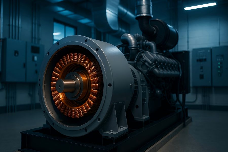
A typical backup generator set pairs a prime mover (diesel or natural-gas engine) with a synchronous alternator. The stator is the stationary iron core with three-phase armature windings where useful AC power is produced. The rotor is the rotating magnetic field source, driven by the engine through a flexible coupling.
Stator
Laminated steel core with evenly spaced slots holding the copper armature windings. The laminations reduce eddy-current loss; the winding layout (pitch, distribution, coil span) shapes waveform quality and voltage regulation.
The stator’s job is to convert the rotor’s moving field into output voltage and to dissipate heat safely.
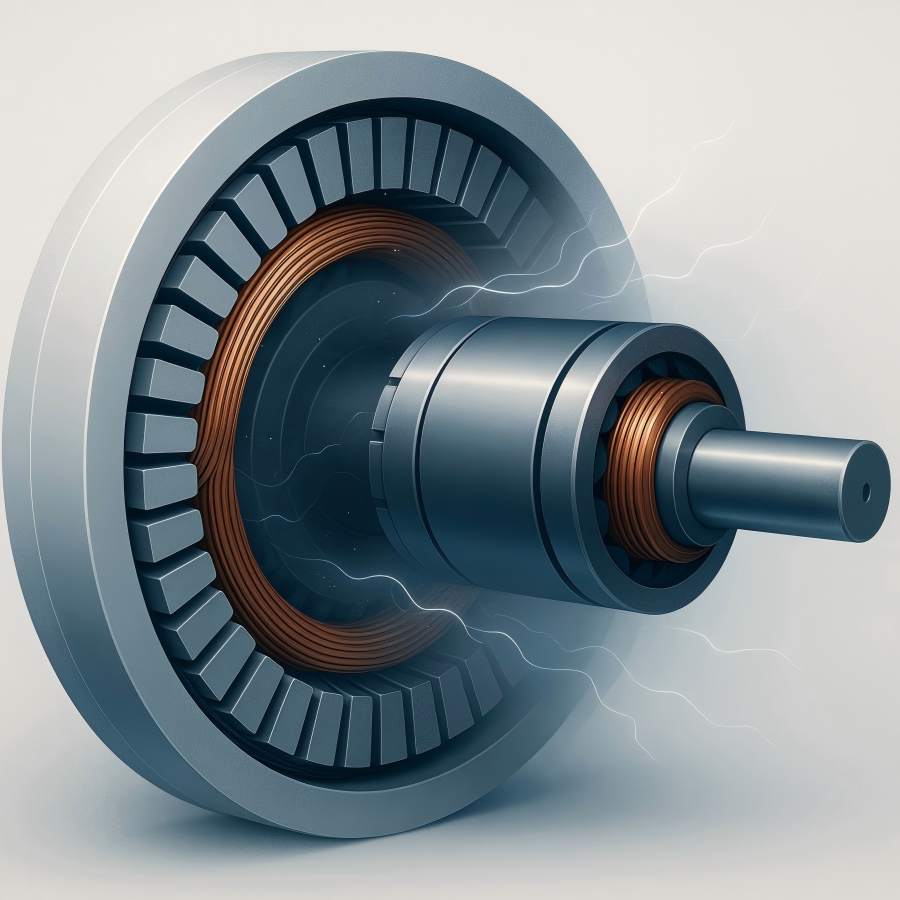
Rotor
In emergency gensets, the rotor is usually a wound field (electromagnet) fed by an excitation system. A smaller subset uses permanent-magnet synchronous generators (PMSGs) for the main machine or for the auxiliary exciter.
Rotor geometry (cylindrical “turbo” style vs. salient pole), field current capability, and inertia directly influence transient response, motor-starting kVA, and stability under step loads.
Together, generator stators and rotors are the machine. All the control algorithms, governors, and AVRs in the world can’t overcome a poorly chosen core geometry, weak excitation margin, or inadequate thermal headroom.
Excitation and voltage regulation
Excitation establishes the rotor’s magnetic field. In brushless emergency alternators, a common architecture is:
- A PMG (permanent-magnet generator) on the same shaft produces a small, stiff AC source.
- An AVR (automatic voltage regulator) rectifies and modulates that PMG power to feed the exciter stator.
- The exciter rotor produces AC that is rectified by a rotating diode bridge (mounted on the main rotor) to deliver DC field current to the main rotor.
- The main rotor’s field cuts the main stator to produce the generator’s output voltage.
This “PMG → AVR → exciter → rotating rectifier → main rotor → main stator” stack matters for reliability. With strong PMG assistance, the alternator maintains excitation even during deep voltage sags (e.g., motor inrush), enabling better ride-through, faster recovery, and higher short-circuit current.
Some designs use auxiliary windings (AREP-style) instead of a PMG; either way, the rotor’s field strength and the system’s CAR (compensation and response) shape how well the stator holds voltage for nonlinear or step loads.
Key takeaway: the rotor provides controllable magnetization; the stator is the workhorse delivering power to the bus. Their interplay—mediated by the AVR—defines voltage stiffness and dynamic performance.
Voltage and frequency under step loads
Emergency systems see harsh transients: UPS rectifiers, chiller and fire-pump motors, elevator starts, MRI power supplies. Two parameters dominate the response:
- Voltage dip and recovery: largely governed by the alternator’s synchronous/reactance profile and excitation reserve.
- Frequency dip and recovery: governed by engine governor performance and rotating inertia.
The stator winding design (pitch, distribution factor, leakage reactance) and rotor design (field current ceiling, damper circuits, transient and subtransient reactance) set the electrical stiffness.
Low subtransient reactance X’ ‘d(typ. 8–15%) generally yields better motor-starting voltage but higher fault currents; higher X’ ‘d softens faults but increases inrush dips. Designers balance these by choosing rotor geometry, winding pitch (often 2/3-pitch to reduce 3rd harmonic), and damper bars to stabilize oscillations.
In practice: A well-matched alternator can sustain a 30–40% step load with voltage recovering to within ±10% in a few hundred milliseconds and to ±5% in 1–2 seconds, provided the engine governor arrests frequency in a similar timeframe. Those numbers depend on alternator size, AVR tuning (V/Hz slope, droop/voltage sensing), and the exact stator/rotor parameters.
Short-circuit behavior and selective coordination
Breakers must trip quickly and selectively during faults—even when the source is a generator with limited short-circuit capacity. Here, the rotor’s magnetic system and the stator’s leakage determine the fault profile:
- Subtransient current (first cycles) can be 3–6 pu of rated current for wound-field machines with strong excitation. It decays to transient and then steady-state levels over tens to hundreds of milliseconds as the rotor’s field and AVR dynamics settle.
- A robust PMG-excited alternator can maintain higher sustained fault current than self-excited types, aiding downstream breaker operation.
- Too high X′′d (i.e., “soft” alternator) can starve protective devices; too low X′′d increases mechanical/electromagnetic stress and requires careful coordination.
Breaker curves, ground-fault schemes, and ATS/SSS transfer logic should be vetted against the alternator’s specific Xd, X’d, X”d, and time constants. Those constants are the fingerprints of the stator/rotor magnetic design.
Motor starting: why alternator design often trumps engine sizing
Starting large induction motors (e.g., 50–400 hp fire pumps or chillers) on generator power is a classic challenge. The alternator must provide high inrush kVA with manageable voltage dip so torque doesn’t collapse. What matters:
- Subtransient reactance X”d: lower is better for inrush voltage support.
- Excitation reserve: the rotor needs headroom to push field current during inrush.
- Winding pitch and distribution: influence waveform under saturation; 2/3 pitch reduces triplen harmonics that interact with motor torque.
- Inertia: a heavier rotor can help frequency stability during the start, complementing the engine flywheel.
Soft starters or VFDs reduce inrush but may introduce harmonics (see next section). In many cases, choosing an alternator with higher motor-starting kVA capability (sometimes expressed as skVA, or as “300% short-circuit for 10 s” style claims) is more effective than simply oversizing the engine. The rotor’s ability to accept high field and the stator’s leakage reactance set the stage.
Soft starters or VFDs reduce inrush but may introduce harmonics (see next section). In many cases, choosing an alternator with higher motor-starting kVA capability (sometimes expressed as skVA, or as “300% short-circuit for 10 s” style claims) is more effective than simply oversizing the engine. The rotor’s ability to accept high field and the stator’s leakage reactance set the stage.
Harmonics and nonlinear loads: UPS, VFDs, and rectifiers
Emergency systems increasingly feed nonlinear loads: 6-pulse or 12-pulse UPS rectifiers, VFDs for HVAC, LED lighting drivers, and switch-mode supplies. These draw peaky currents rich in the 5th, 7th, 11th, and 13th harmonics and triplen components. Alternator consequences:
- Heating: Harmonic currents flow in the stator copper and iron (additional eddy and hysteresis losses) and induce extra losses in the rotor via negative-sequence components.
- Voltage distortion: The alternator’s internal impedance rises with harmonic order, so even moderate harmonic currents can cause significant THDv at the terminals if the source is “soft.”
- Mitigation: Choose 2/3-pitch stator winding to suppress 3rd harmonic voltage; specify alternators with lower subtransient reactance; use 12-pulse or active-front-end UPS; add harmonic filters where appropriate.
Rule of thumb: if total nonlinear load exceeds ~30–40% of generator rating with THDi > 25–30%, select an alternator specifically designed for harmonic duty (extra iron, copper, and thermal margin). Again, this is a stators and rotors problem: copper cross-section, lamination flux density, ventilation, and rotor damper detail all change how the machine copes.
Thermal class, insulation, and duty ratings
Thermal stress is the silent killer. Emergency sets may run infrequently, but when they do, ambient conditions can be worst-case (heat waves, hot generator rooms, dust). Choose stator and rotor insulation systems with headroom:
- Insulation classes are commonly F (155 °C) or H (180 °C). Limit temperature rise to the manufacturer’s stated rise on the chosen class (e.g., Class F system with Class B rise for extra life).
- Cooling: TEWAC or self-ventilated machines must maintain air flow even at part-speed during ramp and cooldown; ensure clear ducts and clean filters.
- Humidity and contamination: Tropicalized varnish, VPI impregnation, and space heaters reduce moisture ingress and partial discharge risk.
Emergency generator duty categories (e.g., continuous, prime, standby) translate to different thermal expectations. For standby (emergency) use, alternators are often designed for short, high-load events and step-load recovery rather than 24/7 maximum efficiency. Sizing conservatively on temperature rise lengthens life—especially for stator windings.
Mechanical integrity: vibration, balance, and bearings
Reliable emergency power depends on mechanical as well as electrical health:
- Balance: Rotors are typically balanced to tight grade levels (e.g., ISO 21940 G2.5). Poor balance or coupling misalignment leads to bearing wear, shaft fretting, and eventual winding damage from vibration.
- Bearings: Most generator ends use rolling-element bearings; grease compatibility, relube intervals, and contamination control matter. Some designs use sleeve bearings on larger frames.
- Torsional interaction: The engine-alternator shaft system has torsional natural frequencies. The rotor’s polar inertia and the engine’s firing order must avoid criticals across the operating range, especially during start/stop and load steps.
Mechanical distress often shows up first as vibration alarms or rising bearing temperatures—catch these early to protect both stators and rotors from collateral damage.
Protection and monitoring
Emergency alternators incorporate protections that reflect real failure modes:
- Over/under voltage & frequency: Protect loads and transfer logic; the AVR limits field, but system-level relays ensure coordination.
- Reverse power/motoring: Prevent engine damage if power flows into the generator (e.g., after fuel loss).
- Overcurrent/ground fault: Coordinate with downstream breakers; residual or zero-sequence CT schemes detect stator ground faults early.
- Diode failure detection: Rotating rectifier diodes can short or open; dedicated monitors or thermal sensors prevent cascading damage to the rotor field.
- Temperature sensors: RTDs or thermistors embedded in the stator slots and on bearings catch hot spots long before insulation is compromised.
In modern systems, these inputs feed predictive maintenance programs that trend insulation resistance, vibration spectra, and temperature gradients.
Commissioning and periodic testing
Good commissioning and routine tests validate stator/rotor health and AVR tuning:
- Insulation resistance (IR) & polarization index (PI): Baseline after installation; trend over time to spot moisture or contamination.
- Surge & hipot tests (as applicable): Validate turn and ground insulation on rewinds or suspicious units.
- Vibration analysis: Establish spectral fingerprints to catch bearing or mechanical issues.
- Load bank tests: Step loads (e.g., 25% increments) to verify voltage and frequency recovery; soak runs to achieve full thermal equilibrium.
- Short-circuit/fault tests (controlled): Confirm coordination assumptions and AVR behavior (with manufacturer guidance).
Environmental hardening
Emergency sets live where the critical loads are—not always in perfect conditions:
- Salt fog / coastal: Stainless hardware, enhanced coating systems, and sealed junction boxes protect the stator and rotating diodes.
- Dusty industrial: Better filtration, pressurized enclosures, and frequent cleaning prevent insulation abrasion and blocked cooling paths.
- Altitude: Reduced air density cuts cooling effectiveness; derate or select larger frames to maintain the same temperature rise.
- High ambient: Check that fans, ducts, and room air-exchange meet the alternator’s cooling requirements; consider class upgrades for varnish and resin.
Common failure modes and how design choices prevent them
Stator winding insulation failure
- Causes: thermal cycling, contamination, vibration.
- Prevention: conservative temperature rise, VPI impregnation, solid slot wedges, clean air paths, embedded RTDs.
Rotor field winding or diode failure
- Causes: over-excitation, thermal runaway, voltage spikes, and mechanical looseness.
- Prevention: adequate heat sinking, diode monitoring, well-tuned AVR with V/Hz limiting, secure winding supports.
Bearing failure
- Causes: contamination, incorrect lubrication, electrical fluting (rare in brushless but possible with harmonics).
- Prevention: correct grease type/interval, shields, grounding when applicable, and alignment checks.
Vibration-induced damage
- Causes: imbalance, misalignment, resonance.
- Prevention: precision balance, torsional analysis, periodic vibration trending.
Robust stator slot support, carefully braced rotor windings, and quality control on lamination stacks drastically reduce these risks.
Control nuances that depend on the machine
- V/Hz limiting: As the engine accelerates, the AVR should limit field to prevent over-fluxing the stator iron at low frequency.
- Reactive droop compensation: For paralleling sets, droop or cross-current compensation ensures VAR sharing; this interacts with the rotor magnetization curve.
- Sensing: Three-phase RMS sensing AVRs handle distortion better than single-phase sensing; better sensing protects stator copper from uneven phase loading under nonlinear conditions.
These are software (control) choices grounded in hardware (machine) realities.

