In electric motor engineering, for engineers involved in motor design, manufacturing, testing, or system integration, misunderstanding these components can lead to specification errors, efficiency losses, or incorrect fault diagnosis.
Basic Anatomy of an Electric Motor
Before analyzing individual components, it is important to understand the fundamental operating principle of electric motors. At their core, all electric motors convert electrical energy into mechanical motion using electromagnetic interaction.
Core Components
Despite enormous variation in size, power rating, and application, most electric motors share the following fundamental elements:
- A stationary structure that establishes or supports a magnetic field.
- A rotating structure that responds to electromagnetic forces.
- An air gap that allows relative motion while maintaining magnetic coupling.
- A mechanical shaft that transmits torque.
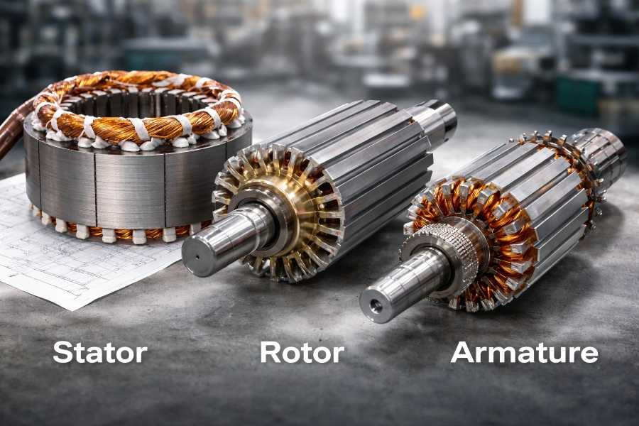
The stator, rotor, and armature occupy distinct roles within this framework.
Electromagnetic Interaction and Motion
Motor operation is governed by two primary electromagnetic laws:
- Lorentz force: A current-carrying conductor in a magnetic field experiences a force.
- Faraday’s law of induction: A changing magnetic field induces an electromotive force.
Depending on the motor type, current may be supplied directly to rotating windings, induced magnetically, or replaced entirely by permanent magnetic fields. These differences largely define whether a component is classified as a stator, rotor, or armature.
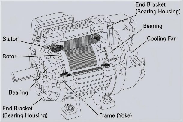
Physical Placement of Components
In most modern radial-flux motors:
- The stator forms the outer stationary ring.
- The rotor revolves with the shaft and is housed inside the stator.
- The armature may be located on either side, depending on motor type.
Quick Reference Table
| Attribute | Stator | Rotor | Armature |
| Motion | Stationary | Rotating | Either |
| Electrical role | Field generation | Torque reaction | EM interaction |
| Location | Outer (usually) | Inner (usually) | Depends |
| Windings | Often present | Sometimes | Always |
What Is a Stator?
The fixed part of an electric motor that creates or directs the magnetic field needed to produce torque is called the stator. Unlike the rotor, the stator does not move mechanically, but it plays an active electromagnetic role.
The stator of the majority of AC and brushless motors has electrified windings that create a revolving magnetic field that interacts with the rotor to create motion.
Stator Construction
From a manufacturing standpoint, the stator is a highly engineered assembly consisting of multiple subsystems.
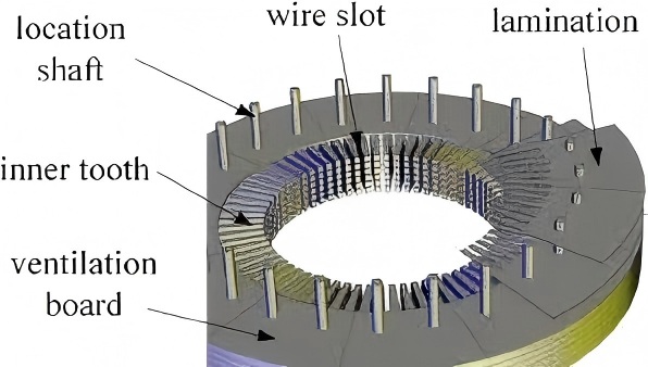
Stator Core Laminations
The stator core is typically built from thin electrical steel laminations, stacked axially to form a cylindrical structure. Lamination thickness commonly ranges from:
- 0.5 mm for standard industrial motors.
- 0.35 to 0.2 mm for motors with good efficiency.
- 0.1 mm or thinner for high-speed or aerospace applications.
Slots and Teeth
The inner circumference of the stator core contains slots separated by teeth. These features:
- Hold and support windings
- Shape the magnetic field distribution
- Influence torque ripple and noise
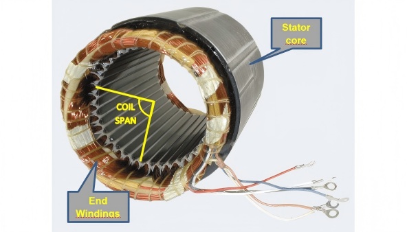
Stator Windings
The stator slots are filled with copper windings that are separated from the core. Depending on the application, windings may be:
- Round wire windings
- Rectangular or flat wire windings
- Hairpin or pin windings
Types of Stators
Stators are classified based on winding arrangement and slot geometry.
Slotted vs Slotless Stators
- Slotted stators offer strong magnetic coupling but introduce cogging torque.
- Slotless stators provide smoother torque and lower noise, at the cost of reduced torque density.
Concentrated vs Distributed Windings
- Concentrated windings simplify manufacturing and reduce end-turn length.
- Distributed windings improve sinusoidal field distribution and efficiency.
The Stator’s Function in System Performance
The stator strongly influences:
- Motor efficiency
- Power factor
- Thermal limits
- Acoustic noise
- Manufacturability and cost
For many motor designs, stator optimization yields greater efficiency gains than rotor changes.
What Is a Rotor?
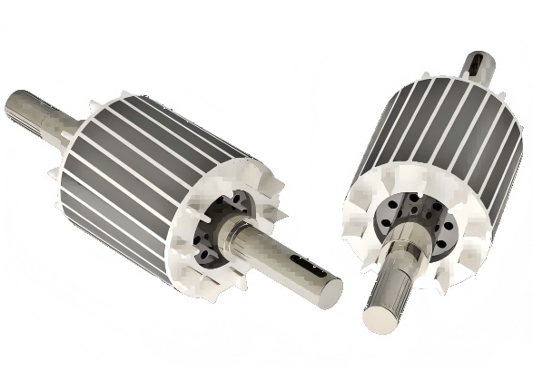
The part of an electric motor that rotates is called the rotor. It is mechanically coupled to the output shaft and converts electromagnetic forces into usable torque.
While the stator creates magnetic conditions, the rotor responds by rotating within that field.
Rotor Construction
Rotor design varies significantly by motor type, but core construction principles remain consistent.
Rotor Core Laminations
Like stators, most rotors use laminated electrical steel cores to reduce losses. Rotor laminations may include:
- Slots for conductors
- Flux barriers (in reluctance motors)
- Magnet cavities (in permanent magnet motors)
Precision in lamination stacking is essential to rotor balance and magnetic symmetry.
Rotor Shaft Integration
The rotor core is typically press-fit or shrink-fit onto a steel shaft. This interface must withstand:
- Centrifugal forces
- Torsional stress
- Thermal expansion
Poor shaft integration can cause vibration, noise, or catastrophic failure.
Typical Rotor Types
Rotor Squirrel Cage
This rotor, which is frequently used in induction motors, is made up of conductive bars that are shorted by end rings. Current is induced, not supplied directly.
Wound Rotor
Contains windings connected via slip rings, allowing external resistance control during startup.
Permanent Magnet Rotor
Uses embedded or surface-mounted magnets to generate a constant magnetic field, eliminating rotor copper losses.
Salient vs Non-Salient Rotors
- Salient rotors have protruding poles and variable air gaps.
- Non-salient rotors offer uniform air gaps and smoother operation.
Rotor Cooling and Mechanical Stress
Rotors experience higher mechanical stress than stators due to rotation. Cooling methods include:
- Internal air channels
- Shaft-mounted fans
- Liquid cooling (high-power machines)
What Is an Armature?
The armature is defined as the component in which electromotive force (EMF) is induced or through which current flows to interact with a magnetic field.
Historically, the term originated in early DC machines, where the rotating current-carrying part was clearly distinguishable from the field system.
Armature vs Rotor: Are They the Same?
It ranks among the most frequent sources of confusion.
- The rotor is the armature of DC motors.
- In AC induction motors, the rotor acts as the armature due to induced currents.
- In BLDC motors, the stator functions as the armature.
Thus, armature describes a functional role, not a fixed physical position.
Armature Construction
Armatures may consist of:
- Laminated cores
- Embedded windings
- Commutators (in brushed machines)
Armature windings are subject to high current density and thermal stress, making insulation and cooling critical.
Key Differences Between Stator, Rotor, and Armature
Functional Comparison
| Component | Primary Function | Motion |
| Stator | Generates magnetic field | Stationary |
| Rotor | Produces mechanical torque | Rotating |
| Armature | Carries current / EMF interaction | Stationary or rotating |
Structural Comparison
- The stator prioritizes thermal stability and insulation.
- The rotor prioritizes mechanical strength and balance.
- The armature prioritizes electrical interaction efficiency.
Electrical Behavior
Armature’s experience:
- High current densities
- Voltage induction
- Commutation or electronic switching
Stators typically experience lower electrical stress but higher thermal loads.
Stator–Rotor–Armature Roles in Different Motor Types
Induction Motors
- Stator: rotating magnetic field generator
- Rotor: induced-current armature
- Armature role: rotor
DC Motors
- Stator: field system
- Rotor: armature with commutator
- Armature role: rotor
Brushless DC Motors (BLDC)
- Stator: energized armature windings
- Rotor: permanent magnets
- Armature role: stator
Synchronous Motors and Generators
Armature and field placement depends on excitation method and application, especially in generators.

