In electric motors, stator and rotor laminations play crucial yet distinct roles in determining overall motor efficiency. Although these components are often mentioned together, their designs, functions, and structural requirements vary significantly.
This article examines the key differences between stator lamination and rotor lamination, highlighting how each contributes to motor performance and energy savings.
Understanding Laminations in Motor Design
The electromagnetic induction theory is the basis for electric motor operation. Two fundamental components of this system are the rotor and the stator. To reduce energy losses due to eddy currents, both the stator and rotor cores are constructed from thin laminated sheets of electrical steel, known as laminations. The magnetic cores that effectively and efficiently direct the magnetic flux are formed by stacking these laminations.
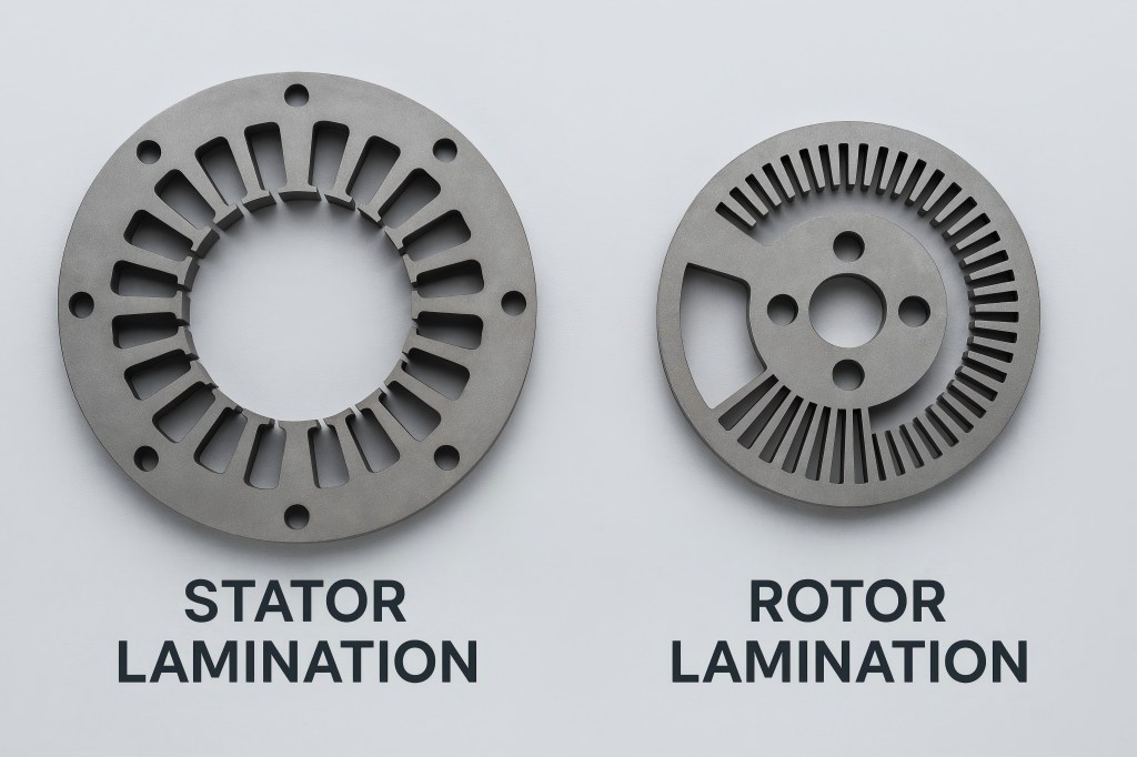
While both stator and rotor laminations serve to minimize core losses and improve efficiency, they are tailored to meet different functional demands. The stator remains stationary and carries the winding that generates a rotating magnetic field, whereas the rotor rotates within the stator’s magnetic field to produce mechanical motion. Each has specific design features that directly impact the motor’s performance.
Key Structural Characteristics of Stator Laminations
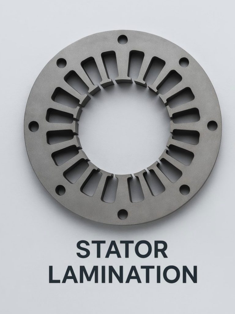
Stator laminations are intended to serve as the motor’s stationary component’s core. They are precision-stamped and assembled to ensure consistency in magnetic performance and mechanical robustness. Some of the defining features include:
- Slot Geometry: Stator laminations include regularly spaced slots for housing the winding conductors. These slots are carefully engineered to minimize magnetic reluctance while allowing optimal space for copper windings.
- Insulation Coating: Each lamination is insulated with a thin dielectric coating to prevent eddy currents from forming between sheets. High-quality insulation also reduces interlaminar corrosion.
- Lamination Thickness: Typical thickness ranges between 0.2 mm to 0.5 mm depending on application requirements. Although thinner laminations lower eddy current losses, they also raise production costs.
- Skewing: In some designs, stator laminations are skewed to reduce cogging torque and magnetic noise, leading to smoother rotation.
Core Attributes of Rotor Laminations
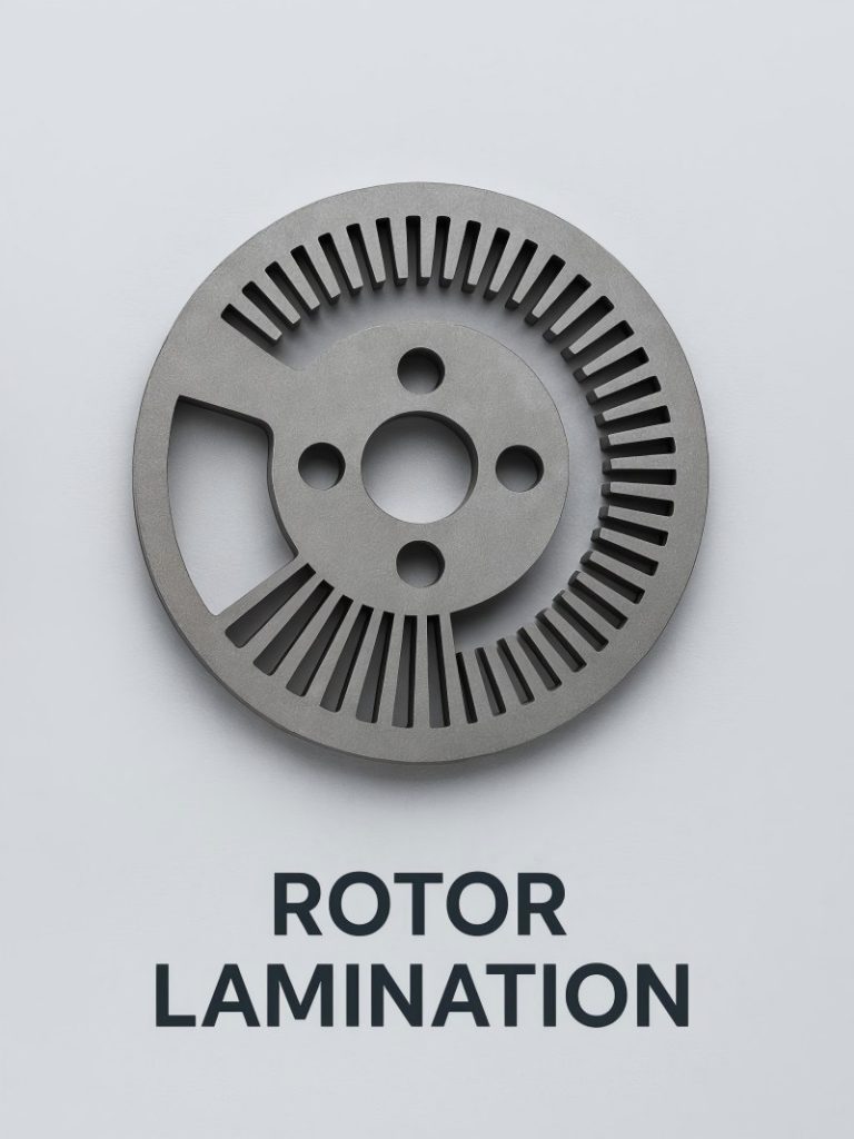
Rotor laminations are tailored for the rotating part of the motor and are generally mounted on a shaft. Depending on the motor type (e.g., induction motor or BLDC motor), the rotor design varies significantly. Common attributes include:
- Slot Type and Shape: In squirrel cage induction motors, rotor laminations have skewed slots that house conducting bars connected at the ends by shorting rings. The skewing helps reduce magnetic locking and torque ripple.
- Lamination Material: Similar to stators, rotor laminations are made of electrical steel, but often require a different magnetic property optimization—sometimes even higher mechanical strength due to centrifugal forces.
- Heat Dissipation: Rotor laminations are subjected to more dynamic mechanical stress and require designs that support better heat dissipation, especially in high-speed applications.
- Balance and Symmetry: Since the rotor is rotating, the laminations must be balanced perfectly to avoid vibrations and ensure smooth rotation.
Comparative Table: Stator vs Rotor Laminations
| Feature | Stator Lamination | Rotor Lamination |
| Function | Forms the magnetic core of the stationary part | Forms the magnetic core of the rotating part |
| Magnetic Role | Carries rotating magnetic field | Interacts with stator field to produce torque |
| Slot Geometry | Designed for winding conductors | Designed for conducting bars or magnets |
| Lamination Thickness | 0.2–0.5 mm | 0.2–0.5 mm |
| Skewing | Often skewed to reduce noise | Skewed to reduce cogging and torque ripple |
| Mechanical Stress | Low | High (due to rotation) |
| Heat Dissipation | Lower thermal demands | Higher thermal demands |
| Manufacturing Tolerance | High precision required | High dynamic balancing required |
| Material Type | Electrical steel | Electrical steel or specialized alloys |
| Common Motor Types | Used in all motors | Varies: Squirrel cage, PM rotor, wound rotor |
How Laminations Affect Motor Efficiency
The use of laminations in stators and rotors drastically reduces energy losses by limiting the formation of eddy currents within the core materials. By segmenting the iron core into thin sheets, the path for circulating currents is interrupted, which lowers heat generation and improves magnetic efficiency.
In stators, lamination accuracy affects the integrity of the magnetic circuit, impacting inductance and power factor. For rotors, particularly in high-speed applications, incorrect lamination balancing or inadequate skewing can lead to vibrations, reduced torque stability, and overheating—all of which decrease motor efficiency.
Additionally, improvements in lamination steel grades (e.g., high-silicon content steels, non-grain-oriented (NGO) steels) and coating technologies have enabled even lower core losses and better frequency performance in modern motors.
Application-Specific Considerations
High-Frequency Motors:
- Require thinner laminations (e.g., ≤0.2 mm) to handle increased eddy current losses at high switching speeds.
- Both stator and rotor cores must be optimized for magnetic permeability and mechanical strength.
Electric Vehicles (EVs):
- Demand high efficiency and torque density.
- Stator laminations use hairpin windings, while rotor laminations often house embedded magnets (for IPM motors).
Industrial Motors:
- Robust stator laminations with standard insulation coatings.
- Rotor laminations are often pressure-mounted and dynamically balanced for long-term durability.
Innovations in Lamination Manufacturing
Precision manufacturing technologies such as laser cutting, high-speed progressive die stamping, and single-slot compound die systems have elevated the quality of both stator and rotor laminations. Automation ensures tight tolerances and minimal burrs, which are critical for ensuring consistent magnetic and thermal performance.
Emerging trends also include:
- Bonded laminations instead of traditional welded or riveted stacks to reduce mechanical losses and noise.
- Thin-gauge silicon steel for motors operating at higher frequencies or requiring better flux control.
- Hybrid stator-rotor designs combining different materials or geometries to suit compact motor platforms like drones or robotics.
Challenges and Future Outlook
Despite advances in lamination technology, challenges remain. Thinner laminations are more expensive and difficult to handle. Also, achieving perfect interlaminar insulation without affecting stack integrity is a complex task.
Future developments may involve:
- Enhanced composite coatings for superior insulation and corrosion resistance.
- 3D-printed laminations or additive manufacturing for prototype and specialized motor designs.
- Greater use of non-silicon electrical steels or amorphous metals to achieve near-zero core loss.
- Research into electromagnetic modeling software is also allowing engineers to optimize lamination layouts before physical prototyping, improving development time and reducing costs.

