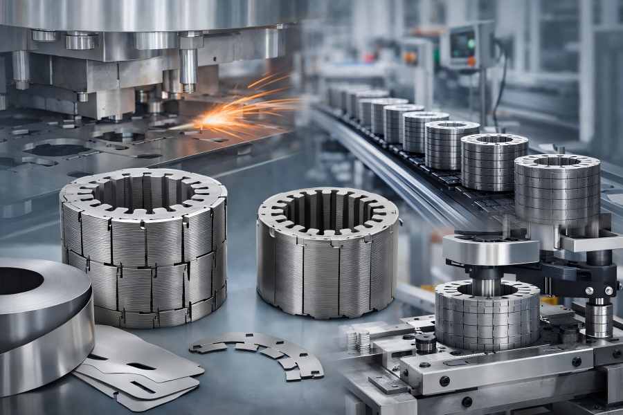
As electric motors advance toward higher efficiency, compact designs, and mass production, lamination stacking has become critical to both performance and cost. Self-locking stator and rotor stacks are popular because they are easy to use, dependable, and appropriate for large-scale production.
What Are Self-Locking Stator and Rotor Stacks?
Self-locking stator and rotor stacks are laminated motor cores in which individual electrical steel sheets are mechanically locked together using integrated interlocking features formed during the lamination stamping process. These features allow the laminations to hold together axially without the need for welding, adhesives, or mechanical fasteners.
Self-Locking (Interlocking) Stacking
In a self-locking stack, each lamination features tabs or slots that interlock with adjacent sheets under axial pressure, forming a stable core.
The locking relies solely on mechanical interference and friction, creating a clean, fast, and repeatable process. Once assembled, the stack acts as a single unit suitable for winding, impregnation, and final motor assembly.
How Self-Locking Differs from Other Stacking Methods
Compared with other stacking techniques, self-locking offers several distinctive characteristics:
- Versus welding: No heat input, no heat-affected zones, and no metallurgical changes to the electrical steel.
- Versus bonding: No adhesives, curing time, or chemical aging concerns.
- Versus riveting: No additional components or secondary fastening operations.
These differences make self-locking particularly attractive for manufacturers focused on process efficiency, cost control, and high production throughput.
Typical Motor Applications Using Self-Locking Stacks
Self-locking stator and rotor stacks are commonly used in:
- Household appliance motors
- Industrial motors
- Pumps, fans, and compressors
- Automotive auxiliary motors (window lifters, seat motors, cooling fans)
- Power tools
In these applications, self-locking provides sufficient structural stability while maintaining competitive production costs.
Why Choose Self-Locking Stacking Technology
The widespread adoption of self-locking stacking technology is driven by a combination of technical and commercial advantages.
Structural Stability Without Additional Fastening
Self-locking laminations distribute axial holding forces across multiple interlocking points around the lamination circumference. This distributed engagement:
- Prevents lamination separation
- Maintains stack integrity during handling
- Supports winding tension and assembly loads
For many motor designs, this level of stability is more than adequate without supplementary fixation methods.
Cost Efficiency and Process Simplification
Self-locking stacking eliminates:
- Welding equipment and energy consumption
- Adhesives, varnishes, and curing ovens
- Secondary fastening operations
By reducing equipment, materials, and labor, self-locking significantly lowers both capital expenditure and per-unit manufacturing cost, especially in large production volumes.
High-Volume Manufacturing Compatibility
Self-locking stacks integrate seamlessly with:
- Progressive stamping lines
- Automated stacking machines
- Inline inspection systems
This compatibility makes self-locking ideal for continuous, high-speed motor core production, where consistency and throughput are critical.
Key Design Features of Self-Locking Laminations
Successful self-locking stacks depend heavily on careful lamination design. Poor design choices can lead to weak locking, excessive stress, or degraded magnetic performance.
Locking Tab and Notch Geometry
The geometry of locking features determines both mechanical strength and stress distribution. Key design parameters include:
- Tab height and width
- Engagement angle
- Edge radius and transition smoothness
Well-designed features provide sufficient holding force while minimizing localized deformation.
Distribution and Number of Locking Points
Locking points are typically evenly distributed around the lamination. Increasing the number of locking points:
- Improves axial retention
- Reduces stress concentration at individual points
However, excessive locking points increase die complexity, stamping force, and tooling cost. A balanced design is essential.
Influence of Lamination Thickness and Material
Lamination thickness directly affects locking behavior:
- Thinner laminations deform more easily and require precise feature control.
- Thicker laminations offer higher stiffness but require greater stamping force.
Material yield strength and coating properties also influence how locking features form and engage.
Design Differences Between Stator and Rotor Laminations
Stator laminations focus on:
- Dimensional stability
- Minimal distortion affecting air-gap uniformity
- Rotor laminations must additionally account for:
- Centrifugal forces during rotation
- Shaft fit and dynamic balance
As a result, locking feature size, shape, and placement often differ between stator and rotor designs.
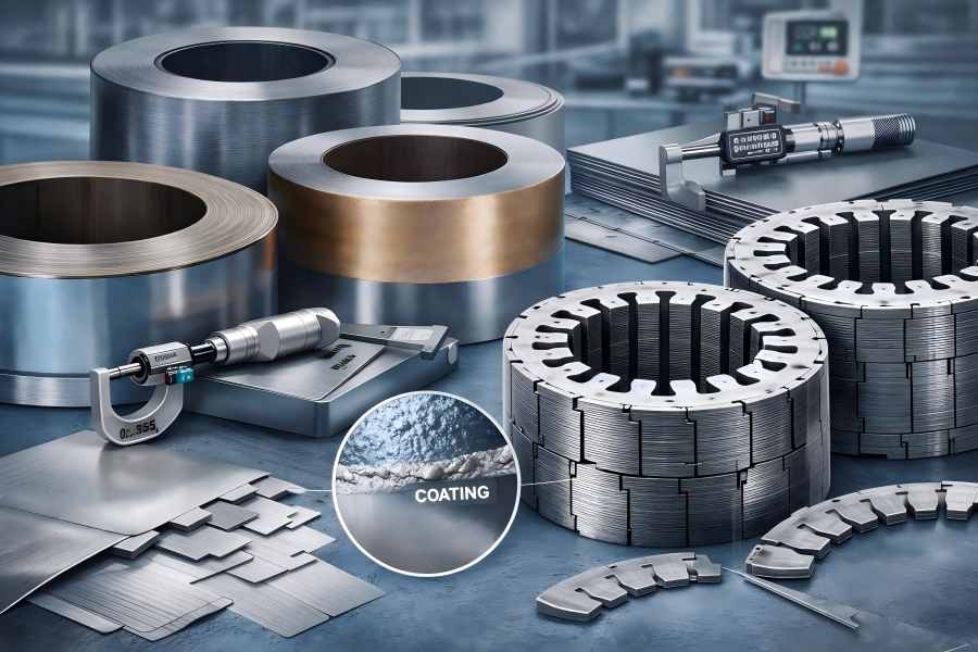
Raw Material Preparation for Self-Locking Stacks
Reliable self-locking performance requires consistent raw material quality.
Electrical Steel Selection
Self-locking stacks typically use non-oriented electrical steel with thicknesses ranging from 0.2 mm to 0.5 mm. Material selection affects:
- Magnetic loss characteristics
- Punching quality
- Locking feature durability
Steel with stable mechanical properties ensures consistent locking engagement.
Thickness Tolerance and Flatness Requirements
Tight thickness tolerance ensures:
- Uniform locking engagement
- Consistent stack height
- Predictable axial compression
Flatness is equally critical. Warped or uneven laminations lead to:
- Poor stack alignment
- Uneven stress distribution
- Reduced locking effectiveness
Surface Insulation Coating Considerations
Electrical steel coatings provide inter-lamination insulation. For self-locking stacks, coatings must:
- Withstand mechanical deformation at locking points
- Maintain insulation integrity after stamping
Brittle coatings may crack, while overly soft coatings may reduce friction at locking interfaces.
Stamping Die Design for Self-Locking Laminations
Stamping die design is one of the most critical factors in producing reliable self-locking stacks.
Progressive Die vs. Compound Die Selection
Progressive dies
- Ideal for high-volume production.
- Combine multiple operations in one continuous process.
- Enable high speed and consistent quality.
Compound dies
- Suitable for lower volumes or larger diameters.
- Simpler structure but lower throughput.
- Most large-scale self-locking stacks are produced using progressive dies.
Precision Requirements for Locking Features
Locking features require extremely tight tolerances. Even small deviations can cause:
- Weak interlocking
- Excessive deformation
- Difficulty during stacking
Precision die machining and accurate clearance control are essential.
Die Material Selection and Wear Control
High-strength die materials are required to maintain feature accuracy over long production runs. Wear control strategies include:
- Optimized punch and die materials
- Surface coatings
- Controlled lubrication
- Regular inspection ensures consistent locking feature quality.
Importance of Die Alignment and Maintenance
Misaligned dies produce inconsistent locking geometry, leading to unstable stacks and higher scrap rates. Preventive maintenance and scheduled calibration are critical for long-term reliability.
Lamination Stamping Process
Once the dies are prepared, lamination stamping becomes the foundation of stack quality.
Single-Slot Stamping vs. Progressive Stamping
Single-slot stamping
- Used for prototypes or large-diameter laminations
- Offers flexibility but lower efficiency
Progressive stamping
- High-speed and automated
- Ensures consistent locking feature formation
- Preferred for mass production
Punching Accuracy and Burr Control
Burrs at locking features reduce effective engagement and increase stress concentration. Burr control methods include:
- Optimized die clearance
- Sharp tooling
- Controlled stamping speed
In some cases, secondary deburring may be required.
Inline Inspection During Stamping
Modern stamping lines often incorporate:
- Vision inspection systems
- Laser measurement tools
These systems detect feature defects and dimensional deviations in real time, preventing defective laminations from entering the stacking process.
Self-Locking Stacking Process Step by Step
After laminations are stamped, the stacking process begins.
Lamination Orientation and Alignment
Correct orientation ensures locking features align properly. Automated feeding systems help maintain consistent orientation and positioning.
Mechanical Interlocking Formation
Axial pressure is applied to engage locking features between adjacent laminations. Care must be taken when using force in order to:
- Locks that are fully engaged
- Steer clear of extreme distortion
Axial Compression Control
Excessive compression can damage laminations, while insufficient compression results in weak locking. Controlled force application ensures consistent stack quality.
Stack Height Consistency Management
Stack height is continuously monitored to ensure compliance with design requirements and winding specifications. In order to preserve process stability, deviations are promptly fixed.
How Self-Locking Ensures Stack Stability
Self-locking stacks rely on mechanical principles rather than bonding or fusion.
Mechanical Holding Force Mechanism
Locking features create interference and friction that resist axial separation. The holding force is distributed across multiple engagement points, improving reliability.
Resistance to Axial Separation
Properly designed self-locking stacks can withstand:
- Handling and transport forces
- Winding tension
- Operational vibration
Long-Term Stability During Motor Operation
For most applications, self-locking provides long-term stability. In high-vibration or high-speed environments, hybrid reinforcement methods may be considered.
Quality Control in Self-Locking Stack Production
Quality control ensures that every stack meets design and performance requirements.
Stack Length and Concentricity Inspection
- Precision gauges and laser systems verify:
- Axial length
- Inner and outer diameter concentricity
Locking Strength Verification
Mechanical tests measure pull-out and shear strength to confirm that locking forces meet specifications.
Flatness and Alignment Measurement
Flatness directly affects air-gap consistency and winding quality. Deviations are identified and corrected promptly.
Sampling and Batch Inspection Procedures
Statistical sampling ensures stable production quality across batches and shifts.
Advantages and Limitations of Self-Locking Stator and Rotor Stacks
| Aspect | Description |
| Advantages | Low cost, high efficiency, clean process, no welding or adhesives |
| Limitations | Stress concentration, lower damping, NVH sensitivity |
| Best Use Cases | High-volume, cost-sensitive motor production |
| Less Suitable For | Ultra-low noise or extreme high-speed motors |
How to Optimize Self-Locking Stacks for Better Motor Performance
Optimization strategies include:
- Improved locking geometry
- Stress relief processes
- Combining self-locking with bonding or welding when necessary

