Across industries ranging from electric vehicles and automation to home appliances and aerospace systems, electric motors serve as the driving force behind motion and energy conversion. The stator and the rotor are two essential parts that are essential to these machines’ functioning.
What Are Stator and Rotor?
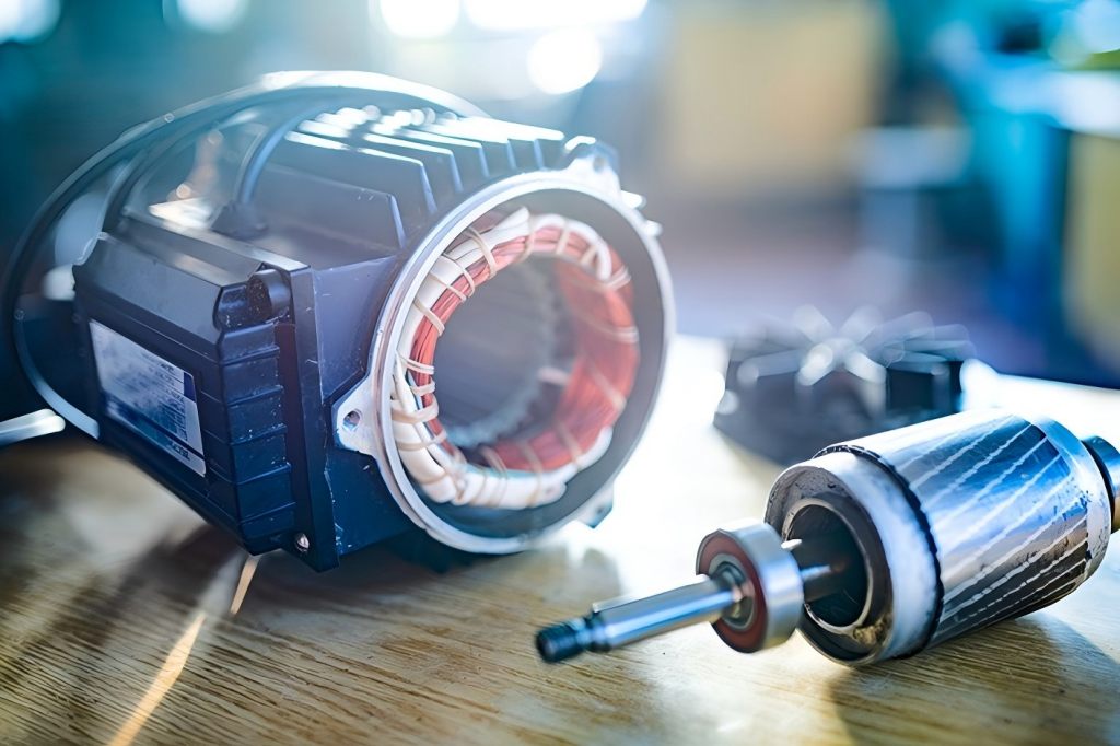
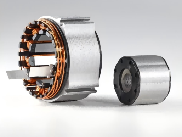
In any rotating electric machine—whether an AC motor, DC motor, or generator—the stator and rotor form the two foundational elements.
- Stator: The motor’s stator is its stationary component. It usually supplies the magnetic field that interacts with the rotor and houses the motor windings or coils.
- Rotor: The revolving part inside the stator is called the rotor. It is connected to the shaft and is responsible for converting the electromagnetic force into mechanical movement.
These two components are positioned concentrically, with a narrow air gap between them, allowing electromagnetic interaction without direct contact.
Fundamental Operation Principle
The operating principle relies on electromagnetic induction. Current creates a magnetic field when it passes through the stator windings. The rotor turns as a result of the torque created by this field’s interaction with the rotor’s magnetic field, which can be either permanent or induced.
Induction motors produce motion by inducing a current in the rotor from the alternating current in the stator. In permanent magnet motors, the rotor contains permanent magnets, and the stator’s field causes it to spin.
Regardless of the type, the stator and rotor must be designed in harmony to ensure optimal performance.
Stator Design
The stator is composed of several key parts:
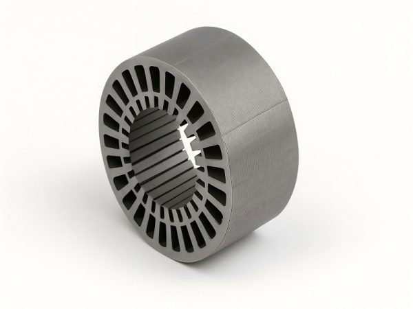
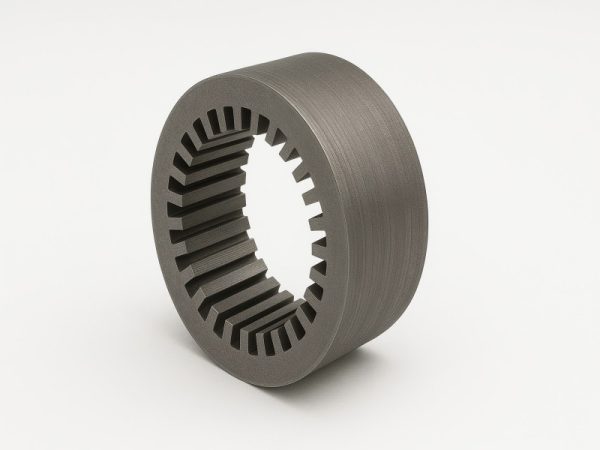
1. Core (Laminations)
Stators are made of stacked electrical steel laminations, which are thin sheets coated with insulating material. This design minimizes eddy current losses and improves efficiency.
- Material: Silicon steel is the most common choice due to its magnetic properties.
- Construction: Laminations are stacked and pressed together to form the stator core, with slots cut into them to house windings.
2. Windings
The windings are typically made of copper or sometimes aluminum and are placed in the core slots. They create the rotating magnetic field when energized with AC or DC current.
- Three-phase windings are used in industrial motors for efficiency and balance.
- Single-phase windings appear in smaller motors like those in household appliances.
3. Insulation and Housing
Windings are contained in a frame that can withstand mechanical and thermal stress and are insulated to avoid short circuits.
Rotor Design:
The rotor is the moving counterpart and typically includes:
1. Core and Shaft
Like stators, rotors use laminated cores to reduce eddy current loss. A central shaft extends from the rotor to transmit mechanical energy to the load.
2. Conductor Types
Depending on the type of motor, there are two primary rotor constructions:
- Squirrel Cage Rotor: A common component of AC induction motors is the squirrel cage rotor. It uses aluminum or copper bars short-circuited by end rings.
- Wound Rotor: Has windings like the stator and is connected to external resistance or control.
3. Permanent Magnet Rotor
In brushless DC (BLDC) or permanent magnet synchronous motors (PMSM), permanent magnets are mounted on or embedded within the rotor. These magnets interact with the stator field directly for higher efficiency.
Interaction Between Rotor and Stator
The air gap between the stator and rotor is one of the most critical design parameters. Although it necessitates tighter manufacturing standards, a smaller air gap boosts the magnetic coupling.
Key Interactions:
- The magnetic field generated in the stator induces current or interacts with the rotor magnetic field.
- The resulting torque rotates the rotor shaft.
- Synchronization between stator field rotation and rotor speed is essential in synchronous motors, while induction motors operate slightly behind the stator field frequency.
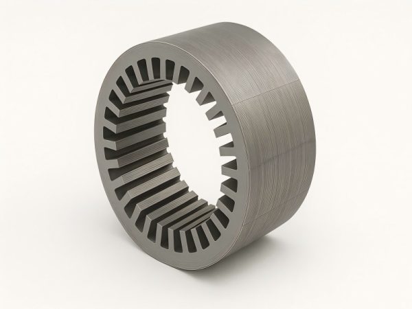
Stator and Rotor Lamination Design
Both stator and rotor cores use laminated steel sheets to reduce energy losses from eddy currents and hysteresis.
Lamination Features:
- Thickness: Ranges from 0.1 mm to 0.5 mm.
- Material Grades: Vary based on electrical loss characteristics.
- Precision Stamping or Laser Cutting is used in manufacturing.
- Slot and Tooth Geometry impact motor performance, noise, and torque ripple.
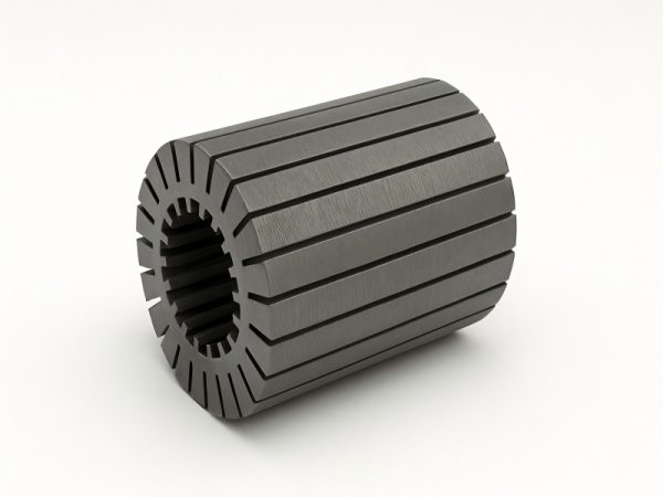
Advanced Stator and Rotor Stack Technologies
Modern motors often use stator and rotor stacks, which are pre-assembled lamination cores.
- Preloaded and bonded stacks ensure uniform stress and better heat dissipation.
- Interlocking tabs or laser welding can enhance structural integrity.
- Use of non-oriented electrical steel or high-silicon alloys improves efficiency.
These stacks contribute significantly to the compactness, performance, and manufacturability of electric motors.
Rotor vs. Stator: Key Differences
| Feature | Stator | Rotor |
| Role | Stationary part generating magnetic field | Rotating part converting EMF to motion |
| Location | Surrounds rotor | Inside stator |
| Contains | Windings, laminated core | Shaft, laminated core, conductor bars |
| Movement | Static | Rotates |
| Power Supply | Directly energized | Induced or magnetically energized |
| Common Materials | Silicon steel, copper | Silicon steel, aluminum, copper, magnets |
| Cooling Needs | Higher heat buildup—requires more cooling | Less cooling needed |
| Complexity | More complex due to winding arrangement | Mechanically simpler in many designs |
Challenges in Rotor and Stator Design
Designing efficient stators and rotors involves several engineering trade-offs:
- Thermal management: Stators generate more heat and need better cooling designs.
- Magnetic saturation: Material selection must avoid early saturation under high loads.
- Noise and vibration: Poor lamination or misalignment can lead to acoustic noise or mechanical wear.
- Manufacturing tolerances: Air gap precision is critical to efficiency and torque performance.
Innovations in Rotor and Stator Technology
Stator and rotor technology is still developing as a result of the growth of electric cars, robots, and renewable energy:
Hairpin Windings
Used in EV motors for higher slot fill factor and thermal performance.
Axial Flux Design
Instead of radial layout, the stator and rotor are flat and parallel—greatly reducing motor footprint.
Soft Magnetic Composites
Emerging material that allows for 3D flux paths and compact designs.
Additive Manufacturing
3D printing of stator/rotor parts can lower material waste and allow unique geometries.
Application-Specific Designs
Design priorities vary across different industries:
- Automotive: High torque density, low acoustic noise, and tight integration with control systems.
- Industrial Drives: Emphasize durability, cost-efficiency, and repairability.
- Aerospace: Weight reduction and fault tolerance are paramount.
- Consumer Electronics: Compact, low-noise, and low-voltage designs dominate.
Maintenance and Reliability Considerations
Although the stator remains static, thermal damage, winding insulation breakdown, or corrosion are potential issues.
For rotors, imbalance, bearing wear, and mechanical misalignment are common failure modes. Advanced diagnostic tools like vibration analysis and infrared thermography help in predictive maintenance.
Future Outlook
Electric motors are expected to dominate future transportation, automation, and even residential applications. As such, the efficiency and material innovation in stator and rotor components are vital.
Stator and rotor laminations are becoming thinner, with enhanced coatings for loss reduction. Stack optimization, combined with digital twin simulations, is allowing engineers to predict lifetime performance with unprecedented accuracy.
In future motor systems, integrated electronics, self-diagnosing materials, and active cooling could further bridge the gap between mechanical systems and smart technologies.

