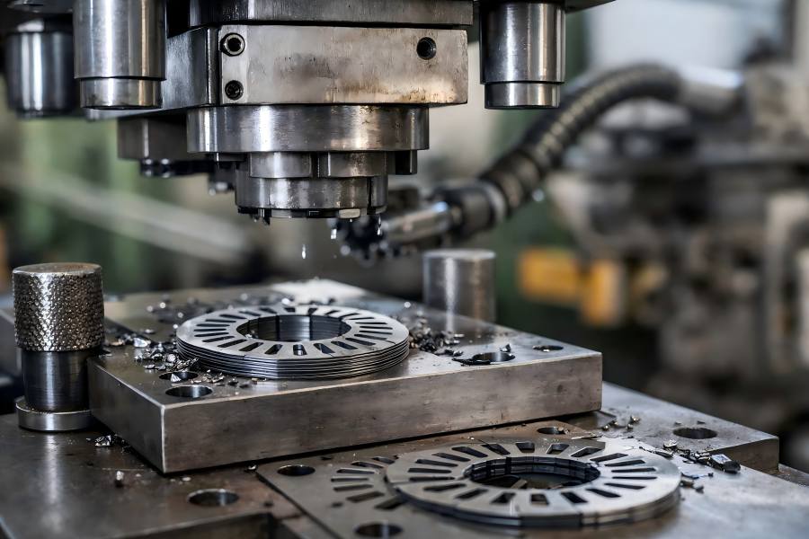
Motor lamination stamping is a foundational manufacturing process that determines the magnetic performance, efficiency, and reliability of electric motors used in EVs, industrial systems, home appliances, and renewable energy equipment.
Because laminations form the core magnetic path, defects in stamping can cascade into costly downstream issues.
1. Burr Formation
Burr formation refers to sharp, raised metal edges remaining on motor lamination outer profiles, internal slots, or holes after stamping, caused by incomplete shearing and excessive plastic deformation during punch penetration and separation in the cutting process.
Causes:
- Incorrect punch-to-die clearance: Excessive or inconsistent clearance leads to incomplete shearing, generating unwanted metal protrusions.
- Worn tooling: Over time, punches and dies dull, exacerbating burr formation due to rough edges.
- Die misalignment: Progressively misaligned tooling increases uneven cutting forces.
- Unstable press force or vibration: Fluctuating press force during stamping results in irregular shearing.
Solutions:
- Calibrate tooling clearance precisely according to material thickness and grade; maintain recommended clearance values.
- Implement scheduled tool sharpening and replacement plans to preserve crisp cutting edges.
- Use high-precision guiding systems and alignment checks before production starts.
- Stabilize press force and monitor vibration with sensors, adjusting settings when irregularities appear.
2. Cracking and Edge Fractures
Cracking and edge fractures appear as visible splits or microscopic cracks along lamination edges or internal cutouts, typically occurring near sharp corners or narrow teeth when local material stress exceeds ductility during stamping operations.
Causes:
- Inadequate lubrication: Lack of proper lubricants increases friction and forces during metal shearing.
- High stamping speed or force: Aggressive press parameters can exceed material ductility limits.
- Sharp internal corners: Die designs with sharp radii create stress concentration points.
- Brittle or low-ductility electrical steel grades: Certain materials are less tolerant to deformation.
Solutions:
- Apply uniform lubrication across strip surfaces to reduce friction and shear stress.
- Reduce press speed and modulate force especially in stages with high deformation.
- Redesign tooling geometry to include fillets and remove sharp corner features.
- Select electrical steel grades with balanced magnetic and mechanical properties to reduce crack susceptibility.
3. Dimensional Inaccuracy
Dimensional inaccuracy occurs when stamped laminations deviate from specified tolerances in outer diameter, bore size, slot width, or tooth geometry, resulting from cumulative errors during progressive stamping and affecting overall core dimensional consistency.
Causes:
- Progressive die misalignment: Wear and improper setup cause cumulative dimensional drift across stamping stages.
- Tool deflection: Punches or dies bending under load due to insufficient rigidity.
- Thermal expansion: Heat buildup in tooling during long production runs alters critical dimensions.
- Inconsistent strip feeding: Inaccurate indexing leads to shifted features.
Solutions:
- Perform regular die and machine alignment checks using precision gauge fixtures.
- Reinforce tooling structure and consider tool steels with higher stiffness to minimize deflection.
- Introduce die cooling systems or controlled ambient conditions to mitigate thermal growth.
- Employ servo motor–based feed systems with closed-loop control for consistent strip positioning.
4. Surface Indentations and Marks
Surface indentations and marks are localized depressions, scratches, or imprinted patterns on lamination surfaces caused by contact with debris, rough tooling, or improper handling during stamping, feeding, or intermediate material transfer stages.
Causes:
- Debris or contaminants: Foreign particles trapped between strip and die leave imprints.
- Poor die surface finish: Rough or scratched tooling transfers surface imperfections.
- Improper strip handling: Slips, drops, or impacts prior to stamping cause pre-marking.
- Incorrect lubrication: Excessive or uneven lubricant causes friction marks.
Solutions:
- Maintain strict cleaning protocols for tooling and strip surfaces to eliminate debris.
- Polish or coat die surfaces to ensure smooth contact with the material.
- Upgrade material handling processes to minimize pre-stamp damage.
- Balance lubrication application to minimize friction without leaving residue.
5. Warping and Distortion
Warping and distortion describe the loss of lamination flatness after stamping, where parts exhibit bending, twisting, or edge curvature due to uneven stress release, unbalanced forming forces, or insufficient strip support during punching.
Causes:
- Uneven stress distribution: Unequal forces during punching create residual stresses.
- Improper blank holder force: Too little force allows buckling; too much force creates material stretching.
- Asymmetric die design: Unequal load paths cause non-uniform deformation.
- Inadequate strip support: Poor guidance or support during punching increases distortion.
Solutions:
- Balance forming forces through refined die design and proper blank holder adjustment.
- Optimize blank holder pressure using test iterations and force monitoring.
- Evenly distribute loads in die cavities to reduce asymmetric deformation.
- Enhance strip support mechanisms to maintain flatness throughout stamping.
6. Insulation Coating Damage
Insulation coating damage involves scratches, peeling, or localized removal of electrical steel insulation layers during stamping, reducing inter-lamination electrical isolation and often originating from abrasive tooling surfaces or uncontrolled friction conditions.
Causes:
- Abrasive tooling surfaces: Rough or corroded dies scrape the insulation.
- Excessive friction: Poor lubrication increases abrasive contact between tools and coating.
- Burr interaction: Existing burrs scrape insulation during handling or stamping.
- Contaminants: Particles embedded in tooling or strip surfaces cut into the coating.
Solutions:
- Apply protective coatings like DLC (Diamond-Like Carbon) and polish tooling surfaces.
- Control lubrication precisely to reduce friction while avoiding excess residue.
- Maintain strict burr control through tooling clearance adjustments.
- Clean stamping areas thoroughly and replace contaminated tooling immediately.
7. Uneven Slot Geometry
Uneven slot geometry refers to variations in slot width, depth, or tooth profile across laminations, typically caused by tooling wear or deformation, which complicates coil insertion and reduces winding consistency during stator assembly.
Causes:
- Progressive die wear: Critical slot-forming features wear faster than cutting edges.
- Punch rigidity issues: Thin or flexible punches deform under load.
- Improper clearance settings: Too tight or too loose punch-to-die clearances distort shapes.
- Material thickness variation: Non-uniform stock thickness results in inconsistent slot formation.
Solutions:
- Employ wear-resistant tool materials (e.g., high-performance steels or coatings).
- Reinforce critical punches with ribs or supports to reduce deflection.
- Verify and adjust die clearance based on material condition and thickness.
- Inspect incoming strip material for thickness uniformity before feeding into presses.
8. Springback and Elastic Recovery
Springback and elastic recovery describe the tendency of stamped laminations to partially return toward their original shape after forming, particularly in bent or formed regions, resulting in deviations from intended geometry after unloading.
Causes:
- High elasticity of electrical steel: Thin steels rebound more significantly after forming.
- Inadequate tool compensation: Dies not designed to account for springback behavior.
- Rapid unloading: Fast press release increases elastic rebound.
- Incorrect forming radii: Sharp bends amplify springback effect.
Solutions:
- Incorporate springback compensation into die design to offset elastic recovery.
- Control forming speeds in critical bends to reduce rebound forces.
- Use forming simulation software to predict springback and refine tool geometry.
- Apply secondary precision forming operations where necessary.

