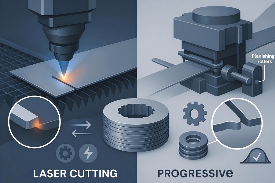
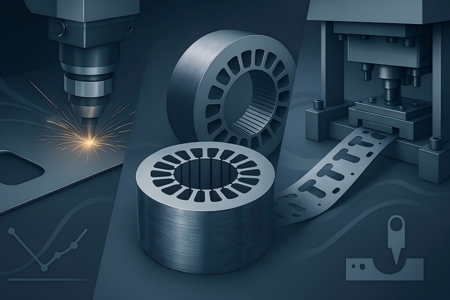
Burrs are small, sharp-edged projections that raise core loss, puncture insulation, and misalign stacks. Here’s a practical, data-driven comparison of laser cutting and progressive stamping for producing burr-free laminations and stacks at volume.
What “burr-free” actually means for motor laminations
For electrical-steel laminations (0.20–0.50 mm), we define “burr-free” as:
- Burr height (BH): ≤ 5 µm on ≥ 95% of measured sites, with max BH ≤ 10 µm.
- Edge roll-over: ≤ 15% of thickness on stamped parts; recast/dross visually nil on laser-cut edges.
- Coating integrity: No breakthrough of C-5/C-6 insulation under 500 V layer-to-layer test.
- Stack flatness: ≤ 0.05 mm per 100 mm OD after bonding/interlock/weld.
- 8 locations per lamination: OD, ID, slot entry/exit, bridge, and two random edges.Optical 2D profilometer (2.5D), 5 µm filter cutoff.SPC on mean BH, max BH, Cp/Cpk for each cavity/tool/laser program.
Executive snapshot
| Criterion | Laser Cutting (fiber, N₂ assist) | Progressive Stamping (carbide, in-die planish) |
| Typical burr height (new/optimized) | 1–6 µm (thin gauges), occasional micro-dross islands | 2–7 µm; increases as dies wear if not planished |
| Edge thermals | Heat-affected zone (HAZ) ~5–25 µm; can pre-cure backlack | No HAZ; cold work zone only |
| Coating risk | Local softening/brown edge if O₂; N₂ eliminates oxide | Possible micro-fracture at roll-over; mitigated by planish |
| Dimensional accuracy | ±0.02–0.05 mm typical on profiles; superb slot fillets | ±0.01–0.03 mm once die is dialed in; excellent repeatability |
| Throughput (per line) | ~1,200–3,600 lams/hr per head (geometry-dependent) | ~9,000–18,000 lams/hr at 150–300 spm (single-out) |
| Changeover & flexibility | Minutes (program switch); no hard tooling | Hours (die change); high-mix requires more dies |
| Unit cost at scale | Higher (energy + time) but no tooling amortization | Lowest at >100k set/year after tooling amortized |
| Best fit | Prototypes, variants, EV custom slots, short-to-mid runs | Long-run, automotive scale, fixed geometry families |
How burrs form—and why stacks amplify the problem
Laser: Burrs arise from recast at low feed/high linear energy, micro-dross from insufficient assist gas, or focus offset causing kerf taper. Laser burrs are usually micro-serrated but shallow; HAZ can soften the coating line and change edge permeability.
Stamping: Burrs follow clearance (punch-die gap), shear burnish %, break height, tool wear, and material anisotropy. Burrs are directional (exit side). Without planishing or alternating, burr-direction can bias stack height and radial growth.
If single-sided burr height is b, and all burrs align, worst-case radial growth is ≈ b (not n×b) because burrs are tiny relative to layer thickness; however, local contact punctures coating, creating interlaminar shorts that raise eddy loss and magnetizing current. Our stacking plans alternate burr orientation (↑↓↑↓) and/or planish to reduce effective burr to ≤ 2 µm at the stack.
Data: typical process capability in our plant
Material set: 0.35 mm M400-50A equivalent; OD 80–260 mm; slot count 36–72; both ID/OD bridges. Backlack C-5 coating.
Table 1 — Edge quality SPC (200-piece capability study)
| Process | Mean BH (µm) | Max BH (µm) | Cp | Cpk | HAZ width (µm) | Roll-over (%t) |
| Laser, 2 kW, N₂ 12 bar, v=32 m/min | 3.2 | 8.4 | 1.67 | 1.45 | 12–18 | 0 |
| Laser, 3 kW, N₂ 16 bar, v=45 m/min | 2.5 | 6.9 | 1.82 | 1.60 | 8–14 | 0 |
| Stamping, new die, 6% t clearance, planish 5% | 3.0 | 7.5 | 1.75 | 1.52 | 0 | 10–14 |
| Stamping, mid-life die, planish 7% | 4.6 | 10.2 | 1.42 | 1.21 | 0 | 12–16 |
Takeaway: Both processes achieve ≤ 5 µm mean and ≤ 10 µm max with proper windows. Laser edges show no roll-over but have a HAZ; stamping shows roll-over but no HAZ.
Dimensional and magnetic consequences
Dimensional: Laser kerf can have 2–5° taper if focus drifts; stamping maintains wall-straightness tied to die land.
Magnetic: HAZ slightly increases local core loss; stamping cold work raises residual stress near the edge. In practice, both effects are second-order compared with coating puncture from burrs. Keeping BH ≤ 5 µm and coating intact matters more than HAZ vs. cold work.
Table 2 — Core-loss delta versus edge condition (stack, 1.5 T @ 50 Hz, normalized)
| Edge condition | ΔPₛᵗᵃᶜᵏ (%) vs. baseline |
| Laser, optimized N₂ cut, HAZ 10–15 µm, intact coating | +0.6–0.9 |
| Stamped, planished, intact coating | +0.5–0.8 |
| Either process, localized coating breach (1% edge length) | +2.5–3.5 |
| Either process, 5% edge breach | +7–9 |
Process windows that actually work
Laser cutting playbook (fiber, N₂)
- Assist gas: Dry N₂ 12–18 bar. O₂ is faster but creates an oxide burr and discolors the coating.
- Linear energy (LE): Keep LE = Power/speed near 0.5–0.8 J/mm for 0.35 mm steel; higher LE increases HAZ/burr.
- Focus: Slight positive offset (+0.1–0.2 mm) to reduce top spatter; auto-focus checks every 200 lams.
- Piercing strategy: Fly-cut when possible; for deep slots, pre-pierce with ramp.
- Pathing: Lead-in/out in scrap bridges; slot entry last to minimize heat stacking.
- Cool-down: Tile-cut sequence to avoid heat accumulation; two-pass micro-tab on fragile webs.
- Coating care: Backlack can pre-cure at edges; keep perimeter edge temp < 250 °C equivalent via speed and tiling.
Progressive stamping playbook
- Clearance: 5–7% of thickness for grain-oriented/HI steels; up to 8% for non-oriented grades to balance burr vs. break.
- Shear burnish target: 30–40% of thickness indicates good penetration; too low → tearing; too high → galling.
- Die materials: Fine-grain carbide punches/dies; DLC-coated strippers for coated steels.
- Planish: 3–7% thickness reduction at edge, post-pierce; reduces BH by 30–60%.
- Lubrication: Ester-based thin film; keep viscosity stable to avoid drag lines.
- Maintenance: Re-hone after 1.5–2.0 M hits or earlier if CpK < 1.33 on BH.
- Burr direction control: Program strip with alternate exit sides or run stack up/down pattern.
Quantifying burr vs. clearance for stamping
Table 3 — Clearance vs. burr (exit side)
| Clearance (% t) | Mean BH (µm) | Max BH (µm) | Notes |
| 4% | 6.8 | 12.4 | Low break, risk of galling |
| 5% | 4.9 | 9.3 | Good for small slots |
| 6% | 3.4 | 7.6 | Balanced; our default |
| 7% | 3.9 | 8.5 | Slightly higher break, still safe |
| 8% | 5.6 | 11.1 | Faster wear, more roll-over |
Rule of thumb: 6% t clearance + planish produces the lowest BH/cost blend for most non-oriented grades.
Laser energy vs. HAZ and burr
Gauge: 0.35 mm; N₂; 100 µm nozzle
Table 4 — Linear energy mapping
| Power (kW) | Speed (m/min) | LE (J/mm) | HAZ (µm) | Mean BH (µm) |
| 2.0 | 20 | 1.00 | 20–25 | 5.5 |
| 2.0 | 32 | 0.63 | 12–18 | 3.2 |
| 3.0 | 45 | 0.67 | 8–14 | 2.5 |
| 3.0 | 60 | 0.50 | 6–10 | 3.0 (micro-notches rise) |
Interpretation: Too high LE inflates HAZ and burr; too low LE raises micro-notch incidence. There’s a sweet spot near 0.6–0.7 J/mm.
Throughput and cost modeling
Assume a 120 mm OD stator lamination; 72 slots; 0.35 mm; annual demand options.
Table 5 — Throughput & cost
| Volume (sets/year) | Laser: lams/hr (1 head) | Laser unit cost (USD/lam) | Stamping: lams/hr | Stamping unit cost (USD/lam) | Tooling amort. (USD) |
| 5,000 | 1,800 | 0.18–0.26 | 9,000 | 0.12–0.16 | 0 (laser), 180k (stamp) |
| 50,000 | 2,400 | 0.11–0.16 | 12,000 | 0.04–0.07 | 180k |
| 500,000 | 3,000 | 0.08–0.12 | 15,000 | 0.02–0.04 | 180k |
One “set” = rotor + stator stacks; lamination count varies by stack height; table shows per-lamination rates/costs.
Includes energy, labor, depreciation; excludes material.
Bottom line: At ≥ 100k sets/year, stamping wins decisively on unit cost/throughput, provided die maintenance keeps BH in spec.
Stack manufacturing considerations beyond the blank
Skew :
- Stamping: In-die skew stacking or index plates can incrementally rotate laminations for low cogging; adds die complexity but no extra edge damage.
- Laser: We skew by programmed rotation per layer during bonding/interlock; edge quality unaffected but cycle time rises.
Stacking & bonding :
Backlack bake pairs well with both processes. Laser’s local heating can pre-activate edge adhesive; adjust oven time by −10–15% for all-laser sets.
Interlock adds small tabs that can create local burrs; planish tabs in-die (stamping) or use micro-tabs (laser) then post-sand lightly (< 2 µm removal).
Post-processing :
Light edge planish (roller) after stamping cuts BH by ~40% without thinning beyond spec.
Vapor honing on laser edges removes micro-dross islands when present.
Demagnetization after either process reduces handling pickup and dusting.
Quality risks and mitigations
| Risk | Process prone | Symptom | Mitigation |
| Coating burn/discolor | Laser (O₂ or high LE) | Brown edge, higher loss | N₂ only, 0.6–0.7 J/mm, tiled heat spread |
| Micro-dross beads | Laser | Speckles on the underside | Higher N₂ pressure, nozzle-to-work distance, lead-outs |
| Roll-over cracking | Stamping | Hairline coating cracks | 6% t clearance, planish 5%, lube control |
| Burr growth with wear | Stamping | BH drifts > 8 µm | Scheduled re-hone, CpK gates, punch corner radius spec |
| Kerf taper | Laser | Tight slot pinch | Auto-focus, positive focus offset, nozzle maintenance |
| Edge notches at corner exits | Both | Micron-scale spikes | Corner slow-down (laser), punch fillet + stripper timing (stamping) |
Case study
Use case A — Mid-volume EV motor (60,000 sets/year).
- Requirement: BH ≤ 5 µm, skewed stator, frequent design updates.
- Outcome: Laser achieves BH 2–4 µm consistently with N₂, quick revisions for slot tweaks, and no tooling cost. Unit cost slightly higher but offset by change agility and saved lead time.
- Winner: Laser for the first 12–24 months or across variant families.
Use case B — High-volume traction motor (600,000 sets/year).
- Requirement: BH ≤ 5 µm, three rotor variants, fixed design, tight PPAP.
- Outcome: Stamping with 6% t clearance + planish + preventive hone holds BH 3–6 µm, CpK ≥ 1.33. Per-lam cost is less than half of laser and press can feed in-die skew and interlock.
- Winner: Stamping once the design is frozen and tooling is amortized.
Practical acceptance criteria we run to
- Burr height: ≤ 5 µm mean; ≤ 10 µm max (both processes).
- Coating puncture test: 500 V DC; no shorts across 100 random edge sites per batch.
- Stack flatness: ≤ 0.05 mm/100 mm OD.
- Dimensional: Slots ±0.02 mm (laser) or ±0.015 mm (stamping) on PPAP; OD/ID concentricity ≤ 0.03 mm.
- Core loss delta: ≤ +1.0% vs. material baseline.
- SPC gates: Cp ≥ 1.67 / Cpk ≥ 1.33 on BH and slot width.
How we decide with customers
- Volume & mix: Below ~100k sets/year or with frequent design changes → laser first. Above that with stable prints → stamping.
- Geometry severity: Extremely fine slot necks or nonstandard fillets often favor laser for edge fidelity; later, we redesign for stampability.
- Timeline: Laser gets parts in days; stamping needs die lead time but pays back in pennies-per-lam savings.
- Magnetics KPI: If your loss budget is tight, we pilot both routes and compare stack loss; coating integrity usually decides it.
- Futureproofing: We often launch on laser, lock performance, then transfer to stamping with matched edges (planish, hone, CpK matched) to keep magnetic results steady.
Engineer’s notes on slot entry and burrs
On stamped parts, design slot entry with micro-radius (R 0.05–0.10) to cut micro-spikes.
On the laser, exit outside the slot (lead-out) to avoid a heat-soaked stop at the slot mouth.
For both, measure BH specifically at tooth tips and slot entries, where coating breach matters most.
Example: stack loss vs burr height
For small burr fractions and intact coating, a linearized model fits well in practice:
ΔP ≈ α · BHmean + β · Lbreach
α ≈ 0.12% per µm BH, β ≈ 0.6% per % of breached edge length.
If BHmean = 4 µm and Lbreach = 0, then ΔP ≈ 0.48%—consistent with Table 2.
A single percent of coating breach adds ≈ 0.6%, overpowering small BH differences.
Implication: Don’t chase 2 µm vs. 3 µm while ignoring rare coating punctures.
Environmental, safety, and housekeeping
- Laser: Fume extraction must capture Fe/Si particulates; no oil, clean shop, minimal swarf.
- Stamping: Lube mist and burr fines require separation/filtration; thorough chip control to protect die edges.
- Edge safety: Specify break-edge ≤ 10 µm (not a chamfer) to maintain magnetic area yet keep handling safe.


