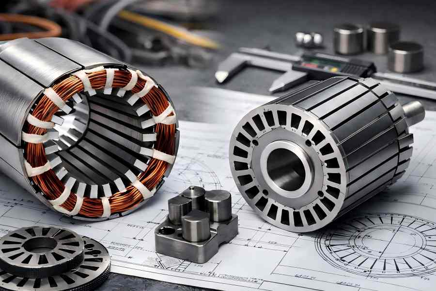
Motor lamination stacks form the magnetic backbone of electric motors, guiding magnetic flux efficiently and minimizing energy losses from eddy currents and hysteresis. By using thin, insulated steel sheets instead of a solid iron core, motors achieve higher efficiency, lower operating temperatures, and longer service life.
While stator and rotor lamination stacks may seem similar, they operate under different physical and electromagnetic conditions. The stator stays stationary and supports windings that generate a rotating magnetic field, while the rotor rotates at high speed, converting electromagnetic energy into mechanical torque and withstanding centrifugal and thermal stress.
What Are Motor Lamination Stacks?
Purpose of Lamination Stacks
Motor lamination stacks serve several critical functions, including:
- Reduction of Eddy Current Losses: By interrupting current loops through insulated layers, the lamination stack minimises the formation of eddy currents, which would otherwise generate heat and reduce efficiency.
- Lower Hysteresis Loss: Through optimized magnetic steel composition, lamination stacks reduce hysteresis loss, which occurs when the material’s magnetic domain changes direction, causing energy loss.
- Improved Thermal Performance: The laminated design helps distribute heat across the stack, preventing excessive heat buildup and enhancing overall motor performance.
- Enhanced Magnetic Efficiency: Lamination stacks direct the magnetic flux along precisely designed paths, maximising the motor’s efficiency.
Without lamination stacking, motors would experience excessive heat generation, reduced efficiency, and premature failure, highlighting the stack’s essential role in motor function.
Basic Structure of Laminations
A typical lamination stack consists of:
- Thin Electrical Steel Sheets: Typically between 0.2 mm and 0.5 mm thick, these sheets are key to reducing core losses.
- Surface Insulation Coatings: These coatings are applied between individual laminations to electrically isolate them, preventing the formation of eddy currents.
- Mechanical Fixation Methods: Various methods, such as interlocking, welding, bonding, riveting, or press fitting, are used to keep the laminations aligned and rigid.
The stacking methods vary depending on the application, speed, and production volume, ensuring that the lamination stack performs optimally in different motor types.
Stator Lamination Stacks
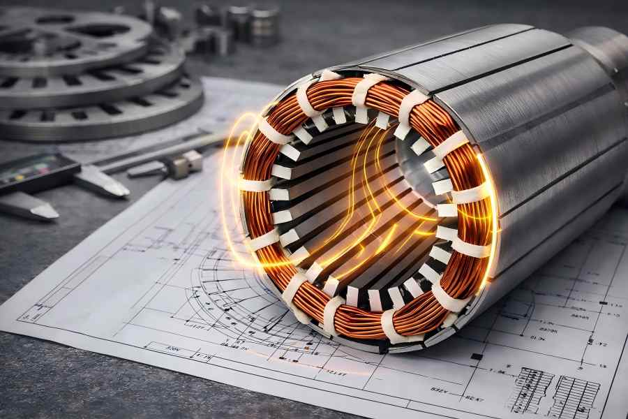
How an Electric Motor’s Stator Works
The motor’s stationary component is called the stator. The magnetic path for the flux produced by energised windings is provided by its lamination stack. A revolving magnetic field produced by the alternating current flowing through the stator windings interacts with the rotor to generate torque. Since the stator does not move, the design of its lamination stack places a strong emphasis on:
- Magnetic Efficiency: Ensuring that the magnetic flux follows the optimal path with minimal energy loss.
- Slot Geometry: Designing the slots to accommodate windings effectively and ensuring proper insulation.
- Thermal Stability: The stator’s lamination stack is designed to handle heat dissipation efficiently to prevent overheating and loss of performance.
Typical Stator Lamination Design
Stator laminations typically feature:
- Inner Slots for Copper Windings: These slots are where copper windings are placed to create the magnetic field.
- Teeth that Guide Magnetic Flux: These teeth guide the flux efficiently along the designed path.
- A Back Iron Section: This section helps direct the return path of the magnetic flux.
Design variables include:
- Slot Count and Shape: This directly affects winding capacity and motor performance.
- Tooth Width and Yoke Thickness: These elements influence the magnetic flux and thermal behavior.
- Stack Length: Determines the power and torque output of the motor.
The geometry of the stator lamination stack impacts efficiency, noise, vibration, and thermal characteristics.
Common Materials for Stator Laminations
Stator lamination stacks are commonly used:
- Non-Oriented Silicon Steel Grades: These materials offer optimal magnetic properties for efficient flux guiding.
- Lamination Thicknesses: Common thicknesses are 0.2 mm, 0.35 mm, and 0.5 mm, chosen based on performance and cost factors.
- High-Performance Insulation Coatings: Coatings such as C3 or C5 are used to reduce eddy currents and improve overall efficiency.
The material selection ensures a balance between minimizing core losses and maintaining manufacturability and cost efficiency.
Rotor Lamination Stacks
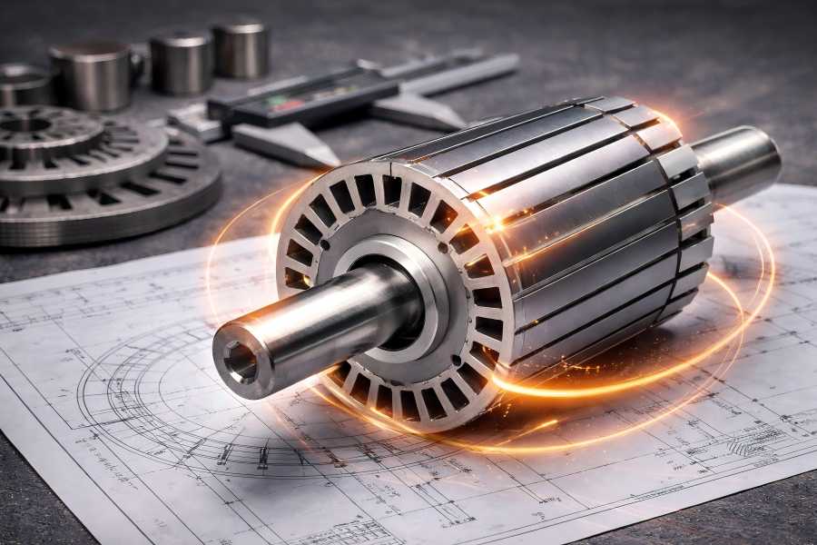
The Rotor’s Function in an Electric Motor
The revolving part of the motor that transforms electromagnetic energy into mechanical motion is called the rotor. Unlike the stator, the rotor undergoes continuous rotation and is subjected to:
- Continuous Rotation: The rotor must endure centrifugal forces and transmit torque at high speeds.
- Thermal Stress: The rotor often operates at elevated temperatures and experiences high thermal stress, which can affect performance.
Depending on the motor type, the rotor may:
- Carry Induced Currents: The rotor of an induction motor uses electromagnetic induction to produce its own current.
- Hold Permanent Magnets: In BLDC and PMSM motors, the rotor holds permanent magnets.
- Use Flux Barriers or Saliency Features: In synchronous reluctance motors, special features like flux barriers guide the magnetic flux.
Typical Rotor Lamination Design
Rotor laminations generally include:
- A Precision Shaft Bore: Ensures proper alignment and secure attachment to the motor shaft.
- Slots for Conductors: Aluminium or copper conductors are placed in these slots to form the rotor bars.
- Magnet Pockets or Flux Barriers: Depending on the motor type, magnets or special features are placed in the rotor for optimal flux management.
Design priorities for rotor laminations include:
- Mechanical Strength: The rotor must withstand high rotational speeds and the forces generated.
- Dimensional Symmetry: Ensuring balance and minimising vibration during operation.
- Secure Retention of Magnets or Conductors: In motors with permanent magnets or conductors, these must be securely fixed to avoid dislodging during high-speed operation.
Common Materials for Rotor Laminations
Rotor lamination stacks often use:
- Silicon Steel: Provides high mechanical strength while maintaining good magnetic properties.
- Slightly Thicker Laminations: Used in high-speed designs to handle the mechanical stresses of fast rotation.
- Specialized Alloys: For extreme environments, materials that withstand high heat or harsh conditions are often required.
To achieve long-term durability, rotor design must strike a compromise between mechanical resilience and magnetic performance.
Structural Differences Between Stator and Rotor Lamination Stacks
Geometry and Dimensional Differences
Stator laminations generally have:
- Larger Outer Diameters: To accommodate the windings and ensure efficient magnetic flux distribution.
- Slots Facing Inward: The slots in the stator face inward to hold the windings, where the magnetic field is generated.
- Fixed Mounting: The stator is securely fixed in place, with no rotational movement.
Rotor laminations typically feature:
- Smaller Outer Diameters: The rotor is designed to fit concentrically within the stator.
- Slots or Magnet Pockets Facing Outward: The rotor’s slots or magnet pockets face outward for magnet or conductor placement.
- Tight Concentricity: Rotor laminations are designed with precise concentricity to maintain balance during high-speed rotation.
Mechanical Requirements
Rotor lamination stacks must withstand:
- High Centrifugal Forces: Due to the rotor’s rotational speed, it experiences strong centrifugal forces.
- Torsional Stress: From torque transmission to the rotor’s mechanical components.
- Dynamic Vibration: High-speed operation leads to dynamic vibrations and potential imbalance.
Stator laminations experience much lower mechanical stresses, with a focus on maintaining rigidity and magnetic stability.
Magnetic and Electrical Performance Differences
Flux Distribution and Magnetic Path
The stator is the primary source of the motor’s magnetic field, while the rotor reacts to this field. Key differences include:
- Stator Laminations: Designed to provide a smooth and uniform magnetic flux path for maximum efficiency.
- Rotor Laminations: Focus on managing flux variation, leakage, and saturation, especially under dynamic conditions.
Loss Characteristics
Stator-related losses:
- Core Loss: Includes losses from hysteresis and eddy currents.
- Copper Loss: From the electrical resistance in the stator windings.
Rotor-related losses:
- Eddy Current Loss: From the rotor bars or magnets.
- Heat from Slip: In induction motors, additional heat is generated due to slip.
Effective lamination design minimizes these losses, reducing the motor’s temperature rise and improving overall efficiency.
Manufacturing Process Differences
Stamping and Cutting Methods
Both stator and rotor laminations are produced using:
- Progressive Stamping: Common in mass production, where precision and speed are crucial.
- Laser Cutting: Used for small batches or prototypes to ensure high precision.
Rotor laminations, however, require stricter concentricity and roundness control, which is critical for high-speed performance.
Stacking and Fixation Techniques
Common stacking methods include:
- Mechanical Interlocking: Ensures that laminations are properly aligned and rigid.
- Laser or TIG Welding: Often used for rotor laminations to ensure strong, secure connections.
- Adhesive Bonding: Used primarily for stator laminations, where mechanical forces are lower.
Rotor stacks require stronger fixation methods to prevent movement at high rotational speeds.
Tolerance and Quality Control Focus
Quality control for stator stacks focuses on:
- Slot Accuracy: Ensuring precision in the slot dimensions for proper winding accommodation.
- Burr Height: Controlling burr height for insulation integrity.
- Insulation Integrity: Preventing any damage to the insulation during manufacturing.
Rotor stacks focus on:
- Runout: Ensuring minimal deviation from the shaft center.
- Balance: Achieving precise balance to minimize vibrations.
- Shaft Bore Concentricity: Maintaining perfect concentricity for rotor stability.
Assembly Considerations
Stator Stack Assembly
Key concerns during stator assembly include:
- Compatibility with Winding Processes: Ensuring proper slot dimensions and insulation during winding.
- Avoiding Insulation Damage: Preventing short circuits or inefficiencies.
- Ensuring Efficient Heat Transfer: Ensuring proper dissipation of heat generated during operation.
Rotor Stack Assembly
Rotor assembly often involves:
- Press-Fitting onto Shafts: Ensuring alignment and secure fixation.
- Die-Casting Aluminium or Copper: Common in induction motor rotors.
- Dynamic Balancing Operations: Essential for rotor assembly due to high rotational speeds.
Rotor assembly is generally more complex and cost-intensive than stator assembly.
Application-Based Differences
Induction Motors
- Stator: Designed to optimize winding efficiency and heat dissipation.
- Rotor: Features a squirrel-cage structure to withstand high thermal and mechanical stresses.
BLDC and PMSM Motors
- Stator: Requires high slot fill and precise winding to ensure efficiency.
- Rotor: Focuses on secure magnet retention and resistance to centrifugal forces.
Servo and High-Speed Motors
- Stator: Uses ultra-low loss laminations for minimal energy waste.
- Rotor: Requires extreme balance and mechanical strength to ensure stable high-speed performance.
Comparison Table: Stator vs Rotor Lamination Stacks
| Attribute | Stator Lamination Stack | Rotor Lamination Stack |
| Primary Role | Generate magnetic field | Convert flux to torque |
| Motion | Stationary | Rotating |
| Mechanical Stress | Low | Very High |
| Slot Orientation | Inward | Outward/Internal |
| Design Focus | Magnetic efficiency | Mechanical strength |
| Assembly Complexity | Moderate | High |
Common Design Challenges and Solutions
| Challenge | Stator Stack Solution | Rotor Stack Solution |
| Excessive Heat | Thinner laminations, better cooling | Improved balance, better heat dissipation |
| Noise & Vibration | Slot geometry optimization | Precision balancing |
| Stack Loosening | Interlocking or bonding | Welding or shrink fitting |
How Manufacturers Optimize Lamination Stacks
Manufacturers optimize lamination stack performance using:
- Advanced Tooling and Die Design: Ensuring precision in every component.
- High-Precision Stamping Equipment: Maximizing consistency and reducing waste.
- Automated Stacking and Inspection: Increasing production speed and accuracy.
- Application-Specific Customization: Tailoring stacks to the motor’s specific needs.
Collaboration between motor designers and lamination suppliers reduces development time and cost.
How to Choose the Right Lamination Stack for Your Motor
Key selection factors include:
- Motor Type and Operating Speed: Helps determine the lamination stack’s requirements.
- Power Density and Efficiency Targets: Influences material and design choices.
- Environmental Conditions: Affects insulation and material selection.
- Production Volume and Cost Constraints: Influences the selection of manufacturing processes.
Choosing the right lamination stack is a strategic decision that impacts the entire motor lifecycle.
Future Trends
Emerging trends in lamination stack design include:
- Ultra-Thin Laminations: For high-frequency motors, improving performance in compact designs.
- Advanced Bonding Technologies: Offering more efficient methods of securing laminations.
- Materials Optimized for EV and Aerospace Motors: For motors that require enhanced performance in specialized environments.
- Integration with Hairpin and Flat-Wire Winding Systems: Offering increased efficiency in motor windings.

