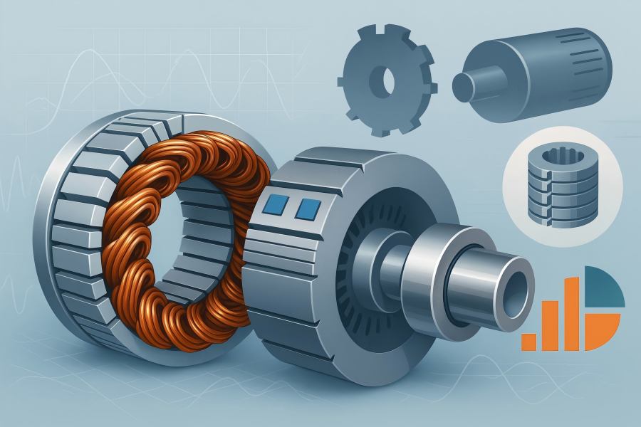
If you strip a generator down to the two components that matter most to its performance and to its price, you end up with the stator and the rotor. Whether you’re sourcing an industrial alternator for a CHP plant, a mid-speed hydro unit, a wind-turbine PMSG, or a brushless exciter train for a gas turbine, the majority of the hardware cost, engineering effort, and schedule risk concentrates in these two assemblies.
Machine topology, rating, and duty profile
Topology sets the baseline bill of materials (BOM) for the generator stator and rotor. A wound-field synchronous generator with a cylindrical rotor looks nothing like a salient-pole hydro machine, and both differ from permanent-magnet synchronous generators (PMSGs) and induction generators.
- Wound-field synchronous (cylindrical rotor, “turbo” style): Expensive forged rotor body, tight tolerances, overspeed testing, and sophisticated balancing dominate. Stator is form-wound with high slot fill and robust end-winding bracing for high electrical stress at medium/high voltage.
- Wound-field synchronous (salient-pole, “hydro” style): Rotor cost is driven by many poles, pole bodies, damper bars, pole shoes, pole-to-rim fastening, and large diameters. Stator iron is thick and segmented; winding is often lap or wave with heavy bracing.
- Permanent-magnet synchronous (PMSG): Magnets (NdFeB or SmCo) become a major materials cost; rotor sleeves (Inconel, titanium, or carbon-fiber) and magnet retention/shielding add cost and test complexity.
- Induction generators (cage): Rotor bars (copper or aluminum), end rings, and brazing/centrifugal casting processes drive rotor economics; stator is similar to a motor stator at comparable ratings.
Beyond topology, rating, and duty matter: apparent power (kVA/MVA), power factor, speed, duty cycle, and overload expectations determine current density, thermal design, and mechanical stiffness, each cascading into material volumes and manufacturing complexity.
Rule of thumb: As machines scale, materials increasingly dominate cost; at smaller ratings, labor, fixtures, and NRE (non-recurring engineering) can be relatively larger.
Electrical steel selection, lamination design, and core building
The stator and (for many machines) rotor cores are stacks of electrical steel laminations. Three aspects drive cost:
- Steel grade and thickness: Lower-loss grades (e.g., high-silicon or cobalt-alloyed steels) and thinner gauges (0.35 mm → 0.27 mm → 0.20 mm) cut core losses and allow higher flux density but raise price per kg and may increase scrap. Thinner laminations also demand better stamping/laser cutting and handling.
- Lamination tooling: Progressive dies reduce per-piece cost at volume but require upfront tooling investment and lead time. Laser cutting is flexible for prototypes and low volume, but per-part cost is higher, and burr/HAZ must be controlled.
- Stacking factor and mechanical integrity: The “stacking factor” (actual steel occupied vs. stack height) affects effective magnetic cross-section. Higher stacking factors require tighter sheet flatness and careful interlam insulation; poor factors inflate the needed stack height (more steel cost). Keyed teeth, dovetail wedges, and ventilation ducts add machining and assembly cost.
For salient-pole rotors, pole core steel, pole shoes, and bolt/rivet patterns add separate cost lines. For induction rotors, cage slots, skew angles (to reduce torque ripple), and end-ring geometry influence both performance and manufacturing effort.
Copper conductors, winding technology, and slot fill
Copper is often the single largest line item in the BOM. Its cost is influenced by:
- Conductor type: Round-wire random-wound coils are cheaper but limited in slot fill and voltage class. Form-wound rectangular conductors (including Roebel bars for large generators) achieve high slot fill, lower I²R losses, and better thermal paths—at higher material and fabrication cost.
- Transposition and eddy-current mitigation: Large, high-current machines need Roebel transposition or strand transposition; this raises coil manufacturing complexity and QA requirements.
- Insulation system: Class F (155 °C) vs Class H (180 °C), mica tapes, glass tapes, ceramic fillers, and VPI (vacuum pressure impregnation) cycles. Higher voltage (e.g., 6.6–15 kV) requires multi-layer turn and groundwall insulation, slot corona protection (SCP), stress grading at end turns, and extended cure cycles—each adding labor and resin cost.
- Slot fill factor: Pushing slot fill from 40–45% into the 55–60% range cuts copper losses and machine length, but increases coil fabrication precision, insertion force limits, and risk of damage—often raising scrap and rework cost.
- Market volatility is non-trivial: copper price swings can move overall generator cost by double-digit percentages. Many suppliers index quotes to LME/COMEX and include hedging or escalation clauses.
Approximate copper mass estimate (stator):
mCu ≈ ρCu × Φcond × Lmean × Nturns
where Φcond = effective conductor cross-section (adjusted for insulation), Lmean = mean turn length including end-winding, Nturns = total turns per phase × phases. Multiply by a slot fill correction and scrap factor (3–8%) to budget realistically.
Rotor materials and manufacturing specifics
The rotor is the risk-concentrated, test-heavy part of many generators.
- Cylindrical (turbo) rotors: Start with a large alloy-steel forging; machining to exacting concentricity and surface finish; slotting for field windings; end-retaining rings (often high-strength austenitic steel); overspeed tests; high-speed dynamic balancing; and NDE (UT, MPI). Forging lead times and QA traceability increase cost—especially above ~50 MVA units.
- Salient-pole rotors: Many poles, each with laminated pole cores, copper field windings, and damper (amortisseur) bars. Costs add up in pole manufacturing, pole-to-rim fastening, and rotor rim fabrication. Large diameters raise mechanical stress and shipping constraints.
- PMSG rotors: Magnets are the elephant in the room. NdFeB magnets dominate and require careful supply-chain management (heavy rare-earth content, coercivity vs. temperature, corrosion protection). Retention sleeves (Inconel/titanium/carbon) and eddy-current shields mitigate losses and mechanical risks at speed. Magnetization fixtures and in-process demag prevention are specialized cost items.
Induction rotors: Copper-bar or aluminum-cast cages, bar brazing/casting, and end-ring integrity. Skew and slot geometry add complexity; high-speed cages demand tight metallurgy control to avoid cracking under centrifugal load.
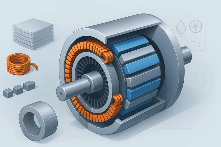
Cooling method and thermal architecture
Thermal design dictates not only materials but also process steps:
- Air-cooled: Lowest capital complexity; costs accrue in larger iron/copper to meet temperature limits and in robust fans/ducting.
- Hydrogen-cooled: Enables higher power density and lower windage loss, but incurs hydrogen seals, seal oil systems, gas panels, purity monitoring, and additional safety compliance—substantial cost and OPEX implications.
- Direct water-cooled stator bars: Hollow conductors, manifolds, leak detection, and cleanliness controls (deionized water, conductivity) add fabrication and QA cost but enable compact high-current designs.
- Integrated ventilation ducts and tooth-top wedges influence lamination design, end-winding spacers, and bracing; each is a cost line.
A hotter allowable rise (e.g., Class H vs F) can reduce copper/iron mass but may shorten insulation life or raise warranty risk; savvy buyers examine lifetime cost, not just first cost.
Mechanical tolerances, dynamics, and balancing
High-speed rotors demand tight runout, concentricity, and surface finish. Balancing to ISO 21940 (often G2.5 or tighter) at multiple planes, plus proof overspeed testing, requires specialized rigs and instrumentation and often consumes a full day or more of shop time per rotor. Large salient-pole units need pole profile matching and careful damper bar fitment to avoid unbalance and vibration. All of this is labor- and test-equipment-intensive.
End-winding bracing systems (blocking, ties, resin-rich components) must withstand electrodynamic forces during faults; engineering and shop-floor time to build and qualify these structures is a quiet but significant cost driver.
Quality assurance, testing, and documentation
Expect a growing share of costs to sit in QA, inspection, and test:
- Incoming materials: Steel mill certs, magnet coercivity and BH curves, copper conductivity, and dimensional checks.
- In-process: Core loss testing (Epstein or ring), EL-CID core interlam fault testing, surge tests on coils, PD (partial discharge) at rated and overvoltage, hipot, insulation resistance polarization index, ring-flux tests, and RTD verification. Water-cooled bars need hydrostatic/helium leak tests.
- Final: Heat runs, overspeed (rotor), no-load loss, short-circuit, efficiency mapping (as spec requires). Each test adds setup time, energy, and engineering sign-off.
- Documentation: Traceability packs, ITPs (Inspection & Test Plans), weld procedures, NDE reports, and as-built drawings. If your application is regulated (utilities, nuclear, offshore wind), documentation can be a double-digit percentage of NRE.
Standards, certifications, and regulatory compliance
Compliance drives design choices and test scope:
- IEC 60034 series / IEEE Std 115, NEMA MG-1, ISO 21940 (balancing), ISO 9001/14001, grid-code compatibility for distributed generation, and sometimes API 541/546 style expectations in petrochemical service.
- Special environments: ATEX/IECEx for hazardous locations, seismic qualifications, and marine/offshore certifications (DNV, ABS). Each adds engineering hours, fixtures, and sometimes alternative materials.
Labor rates, automation level, and plant learning curve
Generators are still craft-heavy products. Plant location, shift structure, and automation level strongly affect cost:
- Automation (coil winding, taping, insertion, varnish curing, laminations stacking robots) amortizes over volume. For custom and low-volume units, manual work and rework dominate.
- Learning effects: First-of-kind (FOK) units carry higher build hours and scrap. Repeats drop sharply after the second or third build as jigs and travelers stabilize.
Supply chain, logistics, and geopolitical factors
- Magnets: Exposure to rare-earth supply risk and export controls; price escalators and long lead times are common.
- Forgings and large stampings: Mill slot capacity and transportation limits (rail clearances, road permits) influence both price and schedule.
Tariffs, VAT/GST, and local content rules can swing landed cost meaningfully. - Freight: Oversized loads require specialized crating, saddles, vibration isolation, corrosion protection (VCI films, desiccant), and route surveys. Insurance premiums rise with weight and value.
Engineering (NRE), customization, and digital deliverables
Even if the electromagnetic design is “known good,” custom frame sizes, terminal box orientations, cooling schemes, or grid-interface requirements trigger NRE:
- Electromagnetic re-optimization, mechanical FEA, thermal CFD, and rotor dynamics.
- Drawings, 3D models, nameplate and rating plate approvals, FAT procedures, and on-site SAT support.
- Controls integration (excitation systems, protection relays, condition monitoring with RTDs, PT100/1000, fiber-optic temperature, and shaft-voltage monitoring).
NRE is often a fixed line item, but can be hidden in overhead; ask suppliers to separate NRE to understand your true repeat unit price.
Warranty terms, reliability targets, and test margins
Longer warranties or aggressive guaranteed performance (efficiency, temperature rise, PD limits) increase factory test time, workmanship standards, and sometimes material overbuild. Some buyers request type tests beyond standards; these reduce your long-term risk but raise the first cost.
Typical cost structure and example model
Exact percentages vary widely, but for medium-to-large wound-field synchronous generators, a plausible starting point for direct manufacturing cost allocation looks like:
Materials (50–70%)
- Electrical steel: 25–40% of materials
- Copper conductors: 30–50% of materials
- Insulation & resins: 5–10% of materials
- Rotor-specific items (forgings, retaining rings, damper bars): 15–30% of materials
- For PMSGs, magnets can be 40–60% of materials (and push the total materials share higher)
Direct labor (15–25%)
- QA/testing & documentation (5–12%)
- Factory overhead & utilities (8–15%)
- Packaging & logistics (2–8%)
- Engineering/NRE (separate for new designs or first-articles)
A simple estimator for first-pass comparison:
Unit Cost ≈ (Csteel × msteel) + (CCu × mCu) + (Cmagnets × mmagnets) + Cinsul + Cmachining + hbuild × rlabor + Ctest + Cpack/ship + (NRE / Nunits)
Where hbuild is build hours and rlabor is loaded labor rate. In early budgeting, engineers often parametrize masses from electromagnetic designs (flux density targets, current density, mean turn lengths) and scale machining/test with active length and rotor diameter/speed.
Practical levers to reduce stator & rotor cost
- Standardize frames and coil sets: Reuse lamination dies, coil forms, and end-winding bracing kits. Even small geometric consistency unlocks learning-curve savings.
- Optimize current density + cooling: A modest increase in current density paired with better cooling (e.g., improved ducting or enhanced VPI) can cut copper mass more than the added cost of thermal hardware.
- Right-size steel grade: Premium low-loss laminations are not always net-positive if your duty cycle is light or efficiency guarantees are moderate. Run a lifecycle cost analysis before “gold-plating” the steel.
- Engineer end-winding length down: Mean turn length (MTL) is a silent copper multiplier. Smart slot-tooth geometry and tighter end-turn radii reduce MTL and copper mass.
- Specify realistic tolerances and test scope: Don’t over-specify balancing grade or extra type tests unless the application truly needs them. Excess conservatism shows up as shop time.
- Choose winding method to match voltage and volume: Random-wound may be fine for lower-voltage compact units; form-wound makes sense at medium voltage or where efficiency warrants high slot fill.
- Use modular stator stacks and pole sets: Facilitates parallel production and shipping, reducing bottlenecks and freight costs.
- Negotiate commodity indexing and hedging: Tie copper and magnet surcharges to indices; clarify adjustment windows to avoid “surprise” change orders.
- Plan for maintainability, not just first cost: Better RTD placement, clean routing of water manifolds, and accessible end-windings shorten service time and reduce lifecycle spend—even if the first cost is slightly higher.
Special cases that swing costs dramatically
- High-speed designs (>3,000 rpm): rotor hoop stresses push material choice (retaining rings/sleeves), QA, and balancing costs up.
- Very low speed / very large diameter (multi-pole hydro): the stator yoke thickness, core building fixtures, and transportation dominate; field assembly labor becomes material.
- Harsh environments: Offshore/marine, hydrogen service, high altitude, or high ambient temperatures demand coatings, sealing, and deratings that change the material/testing mix.
- Grid code or specialty performance guarantees: Tight efficiency, low THD, or low vibration guarantees require extra test time and sometimes overbuild.

