As a China-based manufacturer of motor stator and rotor, we’re often asked which brushless DC (BLDC) topology—inner-rotor or outer-rotor—delivers better performance. The honest answer: it depends on your torque, speed, envelope, and cost targets.
What changes when the rotor moves outside?
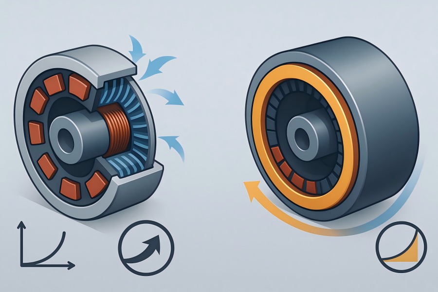
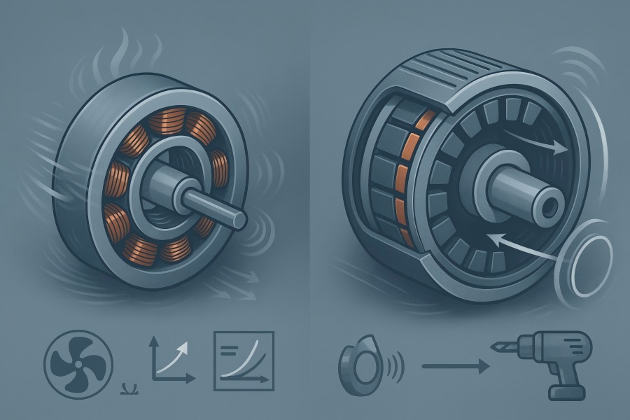
Inner-rotor (IR) motors place the rotor magnets on a central hub that spins inside a stationary stator—a typical BLDC motor stator and rotor layout. These motors tend to run at higher speeds with lower inertia, excel at dynamic response, and cool well because the stator (where copper losses occur) is directly connected to the housing.
Outer-rotor (OR) motors put the rotor as a spinning “can” around the stator, another BLDC motor stator and rotor arrangement. The air-gap radius is larger, so for the same tangential stress, the torque rises, making OR designs attractive for high-torque, low-speed, direct-drive applications. The trade-off is higher rotor inertia and different cooling behavior.
Geometry, torque, and inertia
Torque scaling with radius: Electromagnetic torque is roughly proportional to air-gap shear stress times rotor surface area times radius. Holding materials and current density similar, larger air-gap radius = higher torque. OR designs naturally benefit here.
Inertia trade-off: Rotor inertia J grows with the square of radius. For a thin ring J ≈ m·r²; for a solid cylinder J ≈ ½·m·r². Outer rotors act like rings → higher inertia, which slows acceleration and control bandwidth but yields smoothness.
Thermal path: IR motors conduct copper heat into the housing quickly; OR motors can be excellent too if the can is ventilated or the stator is potted into a heat-spreading back-iron, but design care is needed.
Quick comparison
| Attribute | Inner-Rotor (IR) | Outer-Rotor (OR) |
| Typical speed range | 3,000–30,000 rpm | 100–3,000 rpm |
| Torque density (Nm/kg) | Medium–high (with good cooling) | High at low rpm (larger radius) |
| Power density (kW/L) | High at high rpm | Medium; excellent at low rpm |
| Rotor inertia | Low–medium | Medium–high |
| Dynamic response | Fast (servo-like) | Smooth, less “nervous” |
| Cooling the copper | Direct to housing; strong | Good with potting/fins; needs planning |
| Acoustic noise (NVH) | Low with skew & precision | Very low at low rpm; can “sing” if skew is poor |
| Typical applications | Power tools, pumps, compressors, servos, drones | E-bike hubs, fans, gimbals, robotics joints, turntables |
| Cost drivers | Tight air-gap, high-speed balancing | Larger diameter laminations, magnet can, sleeve |
A sizing example (1–2 kW class)
To expose the geometry trade-off, consider two target operating points:
- Case A (High speed): 1.0 kW at 3,000 rpm → ω ≈ 314 rad/s, torque T ≈ 3.18 N·m.
- Case B (Direct-drive): 1.0 kW at 500 rpm → ω ≈ 52.36 rad/s, torque T ≈ 19.1 N·m.
| Parameter | Inner-Rotor (Case A) | Outer-Rotor (Case B) |
| Air-gap radius (indicative) | 22–28 mm | 45–60 mm |
| Stack length (indicative) | 35–55 mm | 20–40 mm |
| Pole/slot (typical) | 8P/12S, 10P/12S | 14P/12S, 16P/12S |
| Phase current (rms) | 10–20 A (48–72 V) | 15–35 A (36–60 V) |
| Est. copper fill factor | 38–52% | 35–48% |
| Continuous efficiency | 90–95% | 88–93% |
| Rotor inertia (normalized) | 1.0× | 1.8–2.5× |
| Result | Compact, high rpm | Shorter axial length, higher torque per dia |
Electromagnetic design considerations for stator and rotor stacks
Stator core laminations
- Steel grades & thickness: 0.20–0.50 mm electrical steel. Thinner laminations reduce eddy loss at high electrical frequency (IR high-speed motors benefit most).
- Stacking methods: Interlocking tabs, bonding varnish, or welding. We commonly achieve stacking factor of 0.95–0.97 for bonded stacks and 0.96–0.98 for interlocked stacks.
- Skew: 1–2 slot pitch equivalent skew reduces cogging torque and acoustic harmonics. IR tends to use smaller skew angles; OR benefit significantly from proper skew to avoid “singing” at low speed.
- Slot/pole options: IR favors 8/12, 10/12 etc. OR often use higher pole counts (14–28 poles) to boost back-EMF at low speeds and smooth torque.
Rotor stacks & magnet systems
Magnet topology: Surface-mounted (SPM) is common in both IR and OR. For higher power density, interior permanent magnet (IPM) IR designs enable flux-weakening for wide speed range. OR is predominantly SPM (thin arc magnets).
Sleeves & cans: IR: carbon-fiber or high-strength stainless sleeves at very high rpm (to resist magnet burst). OR: rotor “can” (stamped steel or aluminum) with magnet adhesive bond; non-magnetic sleeves to maintain air-gap flux.
Adhesives & retention: High shear strength epoxies (80–150 MPa) with controlled bond-line thickness (0.05–0.15 mm) and cure schedules; mechanical anti-slip features for thermal cycling.
Manufacturing & tolerance data
| Item | Inner-Rotor (typical) | Outer-Rotor (typical) |
| Lamination OD range | 20–200 mm | 40–260 mm |
| Lamination ID tolerance | ±0.010–0.020 mm | ±0.010–0.025 mm |
| Stack height tolerance | ±0.05–0.20 mm | ±0.05–0.20 mm |
| Burr height after deburr | ≤0.02 mm | ≤0.02 mm |
| Dynamic runout (rotor) | ≤0.02–0.03 mm | ≤0.03–0.05 mm |
| Air-gap (small motors) | 0.20–0.50 mm | 0.25–0.60 mm |
| Balancing grade (ISO 21940) | G2.5–G6.3 | G2.5–G6.3 |
| Magnet arc tolerance | ±0.10 mm | ±0.10 mm |
| Slot fill factor (wound stator) | 38–52% | 35–48% |
Thermal behavior and continuous ratings
IR: Copper loss (I²R) is rejected directly into the housing via the stator teeth and yoke. With aluminum housings and tight interference fits, IR motors sustain higher continuous current density (e.g., 3–8 A/mm² in slot copper cross-section, depending on cooling).
OR: The stator is internal and may rely on conduction through back-iron and potting to the base. Proper resin fill and metallic thermal paths are vital. Expect 2–6 A/mm² continuous current density unless forced airflow or liquid cooling is added.
Thermal design knobs: copper fill, slot liner materials, impregnation quality, yoke thickness, tooth tip width, and heat-spreading features such as fins. We typically target winding rise ≤80–105°C over ambient at continuous rating with Class F/H insulation.
Efficiency and losses
- Copper losses: A function of current and slot design. IR can afford higher current density (better cooling), enabling compactness. OR keeps current density moderate, leveraging radius for torque instead.
- Core losses: Increase with frequency and flux density. High-speed IR motors benefit from 0.20–0.27 mm laminations and careful tooth-tip flux shaping. Low-speed OR motors can accept 0.35–0.50 mm laminations without penalty.
- Mechanical losses: Bearing and windage uplift at high rpm; IR at 20k–30k rpm demands low-loss seals and precise balance. OR is typically low rpm → modest mechanical loss.
- Indicative peak efficiencies: IR: 90–95% in 0.3–5 kW sizes with strong cooling. OR: 88–93% in 100 W–1.5 kW direct-drive sizes, rising with optimized can and magnet arcs.
Dynamics, control, and NVH
- Bandwidth: IR’s lower rotor inertia (and usually lower pole counts) supports fast current and speed loops—ideal for servos, CNC spindles, power tools.
- Smoothness: OR’s higher pole counts and inertia produce silky low-speed motion—excellent for gimbals, robotics joints, and fans.
- Cogging & ripple: Skew, fractional-slot windings, and tooth shaping are crucial in both. We often target cogging ≤1–3% of rated torque for precision applications.
Reliability and safety
- Sleeving: At very high surface speed (tip speed), IR rotors may require carbon-fiber sleeves; we perform burst margin analysis and proof-spin tests.
- Adhesive aging: OR cans demand rigorous surface prep (grit blast + chemical clean), controlled adhesive thickness, and humidity/temperature cycling.
- Corrosion: Coatings on laminations (insulation Class C5), magnet plating (Ni, Ni-Cu-Ni), and stainless cans increase life in humid or salt-spray environments.
Application mapping
| Application | Preferred Topology | Why |
| E-bike hub, scooters | Outer-rotor | High torque at wheel, quiet, direct-drive |
| HVAC & server fans | Outer-rotor | Large diameter, low rpm, excellent smoothness |
| Gimbals & camera stabilizers | Outer-rotor | Smooth low-speed torque, high pole count |
| Collaborative robot joints | Outer-rotor | Direct-drive torque in a short axial length |
| Drones (propulsion) | Inner-rotor (or outrunner in hobby) | High power density; rapid throttle response |
| Power tools, grinders | Inner-rotor | High speed, quick accelerations |
| Pumps, compressors | Inner-rotor | Cooling and efficiency at medium–high rpm |
| Direct-drive turntables | Outer-rotor | High inertia smoothness, low cogging |
| Industrial servos | Inner-rotor (IPM) | Wide constant-power speed range, flux-weakening |
Cost & supply chain drivers
- Lamination diameter: OR cores are larger in diameter; per-piece lamination cost is higher, but stack height can be shorter. Die set size and punch press tonnage scale with diameter.
- Magnet volume: OR often uses more total magnet arc length to cover the larger circumference; IR can trade magnet volume against speed and flux-weakening (IPM). Magnet price sensitivity is higher for OR when using many poles.
- Sleeves and cans: An OR can adds fabrication steps (deep-draw, roll-form, or machined ring + weld). IR sleeves are specialized but used mainly for high-speed variants.
- Winding method: Concentrated windings reduce copper scrap and automate well; distributed windings improve waveform quality at cost of complexity.
Example bill of characteristics
| Metric | IR, 54 mm OD stator, 48 V | OR, 110 mm OD rotor can, 48 V |
| Rated speed | 6,000 rpm | 600 rpm |
| Rated torque | 3.5 N·m | 18 N·m |
| Peak torque (5–10 s) | 10–12 N·m | 42–50 N·m |
| Continuous current density | 5.5 A/mm² | 3.8 A/mm² |
| Efficiency at rated | 93% | 91% |
| Cogging (as % rated T) | 1.8% | 1.2% |
| Rotor inertia | 2.1×10⁻⁴ kg·m² | 4.6×10⁻⁴ kg·m² |
| Air-gap | 0.30 mm | 0.40 mm |
| Lamination thickness | 0.27 mm | 0.35 mm |
| Cooling | Housing-conducted + fan | Potting + can fins |
| Balancing grade | G2.5 | G2.5 |
Design checklist (what to lock down before choosing IR vs. OR)
- Torque–speed point(s) and duty cycle: Continuous and peak torque, run time at each, allowable temperature rise.
- Envelope constraints: Radial space vs. axial length. OR thrives with more diameter; IR thrives with more length.
- Control requirements: Required acceleration/deceleration, position bandwidth, and ripple. If you need tight servo behavior, IR or a low-inertia OR with fewer poles and a lightweight can may be better.
- Acoustic limits: Maximum dBA at distance, dominant frequencies to avoid; consider skew and fractional slot/pole choices.
- Ingress & environment: Humidity, salt-spray, shock/vibration. Decide on coatings, seal types, and potting.
- Manufacturing volumes & cost targets: Tooling strategy (progressive dies vs. laser for prototypes), magnet grade availability, sleeve/can process.
How we manufacture stator and rotor stacks
- Lamination stamping: Progressive tooling for volume, laser/waterjet for prototypes. We manage flatness ≤0.03 mm per 100 mm and burrs ≤0.02 mm after deburring.
- Stacking & bonding: Interlock or bonded stacks with a stacking factor ≥0.96. Controlled adhesive application eliminates axial “soft zones.”
- Skewing: Segmented skew stacks or skewed punch patterns for cogging reduction.
- Machining & ID/OD finishing: Post-stack grind/turn to guarantee air-gap tolerance bands.
- Rotor assembly: Magnetization patterns (radial for SPM; tailored for IPM), adhesive control (0.05–0.15 mm bond line), sleeve/can installation, cure, and 100% dynamic balancing.
- Insulation & winding support: Slot liners (Nomex/aramid), wedges, and VPI for vibration durability.
- End-of-line tests: Back-EMF constant (line-line), phase resistance & inductance, no-load current, cogging torque trace, runout, hipot, surge, and thermal soak.
Common pitfalls and how to avoid them
| Pitfall | Why it hurts | Mitigation |
| Over-tight air-gap specs | Drives cost and scrap sharply | Co-optimize magnet grade, slot fill, and skew; set realistic runout & gap |
| Ignoring rotor burst margins (IR) | Sleeve failure risk at high tip speed | Carbon-fiber sleeves, FEA stress check, proof-spin testing |
| Under-skewed OR designs | Low-speed acoustic “singing” | 1–2 slot pitch skew or fractional-slot winding |
| Poor thermal path in OR | Chokes continuous rating | Resin potting to back-iron, can fins, thermal pads |
| Excessive pole count | High copper loss at high electrical frequency | Balance poles vs. frequency; use thinner lams if needed |
| Magnet adhesive starvation | Magnet creep under shock/heat | Surface prep, controlled bond thickness, proper cure |
Selecting the right topology
| Requirement | Better Choice | Notes |
| High torque at low rpm, direct-drive | Outer-rotor | Large air-gap radius gives torque without a gearbox |
| Tight servo response, rapid accel/decel | Inner-rotor | Lower inertia, easier flux-weakening |
| Small diameter, more axial length available | Inner-rotor | Stack length is an efficient lever |
| Very low acoustic noise at low rpm | Outer-rotor | With good skew and pole selection |
| Highest continuous rating per kg at high rpm | Inner-rotor | Cooling path and thin lams help |
| Minimal axial length (“pancake” form) | Outer-rotor | Short stator stack, larger diameter |
| Lowest magnet mass for given speed power | Inner-rotor (often) | Especially with IPM and flux-weakening |
| Simplest mechanical integration | Depends | OR integrates nicely as hub; IR as cartridge |
Custom data we can deliver with quotes
- Electromagnetic model outputs: torque–speed curve, back-EMF constant, cogging (% of rated torque), predicted efficiency map.
- Stack drawings: lamination OD/ID, tooth geometry, skew angle.
- Thermal model summary: allowable continuous current, temp rise vs. ambient, proposed cooling features.
- Costed BOM options: magnet grades (e.g., N35–N52 or ferrite for cost), sleeve/can materials, winding method.


