Everything from home appliances to industrial pumps is powered by electric motors. While failures often result from worn bearings or insulation breakdown, one critical issue is misalignment between the stator and rotor. When misaligned, the imbalance leads to performance issues, efficiency losses, and costly breakdowns.
Understanding Motor Anatomy: Stator, Rotor, and Air Gap
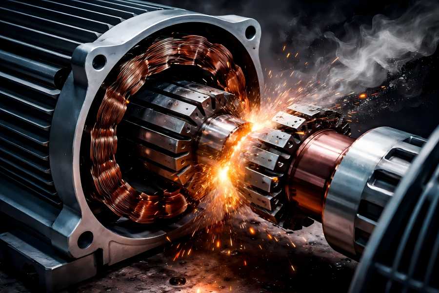
To appreciate the impact of misalignment, it helps to understand how a motor is constructed and how its parts interact:
- Stator: The motor’s stationary exterior component, which is made up of windings or magnets that create the magnetic field.
- Rotor: The internal rotating part that rotates as a result of the stator’s magnetic field.
- Air Gap: The precisely engineered space between stator and rotor that allows rotation without contact while maintaining optimal electromagnetic interaction.
In an ideal motor, the rotor and stator are concentric, with a uniform air gap around the circumference. This balance ensures smooth torque production, stable magnetic field distribution, minimal vibration, and efficient energy conversion.
When alignment is disturbed due to errors, wear, or thermal distortion, misalignment alters the air gap, disrupts the magnetic field, generates abnormal forces, and leads to performance degradation and mechanical failure.
What Is Stator–Rotor Misalignment?
Stator-rotor misalignment, to put it simply, is the result of the rotor’s centerline diverging from the stator’s. This deviation can be:
- Axial: The rotor is shifted forward or backward relative to the stator on the motor’s axis.
- Radial: The rotor is offset sideways relative to the stator, creating uneven air gaps.
- Angular: The rotor is tilted relative to the stator’s axis, meaning the central shafts are not parallel.
Each type of misalignment creates irregularities in magnetic flux, air gap symmetry, and mechanical load paths, leading to consequences that range from subtle performance loss to catastrophic failure.
Common Causes of Stator–Rotor Misalignment
There is no single root cause of misalignment. Instead, a variety of mechanical, manufacturing, and operational factors can contribute:
Manufacturing Tolerances and Assembly Errors
During production, if the stator core and rotor are not machined to precise tolerances or correctly assembled, even a small angular or radial deviation can be introduced.
For example, inaccurate positioning sizes or inconsistent core lengths can result in misalignment right from the factory floor. Similarly, if the rotor is assembled with a slightly off-center key or shaft, this initial imperfection carries through into operation.
Manufacturing quality control is therefore the first defense against misalignment, requiring strict dimensional checks, measurement of core concentricity, and validation of assembly procedures.
Loose or Incorrect Bearing Installation
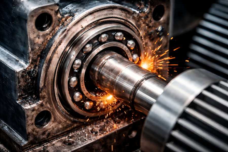
Bearings support the rotor within the stator. Improper installation, such as incorrect seating, uneven preload, or worn races, can cause the rotor to wobble, shifting its centerline and distorting the air gap. This is a common mechanical cause of misalignment in operational environments.
Thermal Distortion and Uneven Heating
Electric motors frequently run at a range of temperatures and loads. When components heat unevenly, such as the stator winding heating differently than the rotor assembly, thermal expansion can alter material dimensions. This uneven thermal growth may cause the rotor to shift slightly, particularly during prolonged or high-temperature operation.
Shaft Deflection and Mechanical Stress
Heavy loads, excessive vibration, or torque spikes can physically deform the motor shaft. Bending of the shaft causes the rotor’s path to deviate from its ideal axis, creating angular misalignment. A flexed shaft also places uneven loads on bearings and other mechanical interfaces, compounding wear and increasing the likelihood of misalignment over time.
Soft Mounting or Structural Instability
Motors must be securely mounted on stable bases or frames. If the mounting surface is weak, uneven, or subject to continual vibration, the entire motor assembly may shift, altering stator–rotor alignment. Soft feet, uneven foundation bolts, or base plate distortion are common culprits in industrial settings.
Component Wear and Maintenance Neglect
Over time, rotor shafts, bearing housings, and housing bores wear down due to friction, corrosion, or contamination. Worn parts have more “slop” or play, allowing the rotor to shift out of its intended position. Routine maintenance is critical to catch early signs of wear that could eventually compromise alignment.
Why Misalignment Matters
Misalignment between the stator and rotor is not simply a mechanical curiosity — it has real, measurable impacts on motor performance and reliability. Some of the most common consequences include:
Uneven Magnetic Field and Air Gap Distortion
When the stator and rotor are not properly aligned, the air gap around the rotor becomes uneven. This causes irregular flux distribution in the magnetic circuit, which in turn generates fluctuating torque and forces within the motor. Instead of a smooth, balanced electromagnetic field, an eccentric field develops that can stress both electrical and mechanical components.
Increased Vibration and Noise
Distorted magnetic forces and uneven mechanical loads create excessive vibration, which often presents as noise during operation. Vibration does more than just produce an audible symptom — it accelerates wear on bearings, seals, and other connected systems, leading to a vicious cycle of deterioration and further misalignment.
Premature Bearing Failure
Bearings are designed to support smooth rotation under predictable loads. When misalignment introduces lateral and radial forces that bearings are not engineered to handle, wear accelerates dramatically. This can lead to premature bearing failure, noise, increased friction, and ultimately a seized rotor.
Reduced Efficiency and Increased Heat
Misalignment causes increased electrical losses as the rotor “chases” an uneven magnetic field. Reduced efficiency results from the motor needing to draw more current in order to produce the same amount of torque. Increased current flow and friction also raise internal temperatures, which weakens insulation, accelerates component aging, and can lead to winding failure.
Motor Performance Degradation
Motors affected by misalignment often exhibit slower speed, lower torque, and inconsistent operation. These performance symptoms can be mistakenly attributed to other issues unless misalignment is considered and measured. Over time, these performance degradations can have ripple effects throughout the entire machine or production line.
Shaft and Coupling Damage
When the rotor is not centered, additional stress is placed on the shaft and couplings connecting the motor to driven equipment. This stress can lead to shaft bending, fatigue cracks, or coupling wear, resulting in more expensive and time-consuming repairs.
Symptoms and Early Warning Signs
Identifying misalignment early can save significant downtime and repair costs. Some common signs include:
- Unusual noise or excessive vibration during operation: a common sign that mechanical components are misaligned.
- Higher than normal energy consumption: misalignment increases electrical demand for the same mechanical output.
- Irregular or fluctuating motor speed: misaligned motors may not maintain constant rotational speed under varying loads.
- Overheating of bearings or winding areas: thermal images or temperature readings may reveal hot spots.
- Premature wear patterns on bearings and seals: visible evidence during inspection suggests mechanical imbalance.
Operators and maintenance teams should monitor vibration, sound, temperature, and current draw as part of routine checks. Modern condition monitoring systems can even alert teams to deviations before performance breaks down.
Diagnosing Misalignment
Accurate diagnosis requires systematic evaluation. Common diagnostic methods include:
Visual and Mechanical Inspection
Physically inspecting the bearing housing, shaft alignment, and mounting surfaces can reveal any misalignments or loose components. Additionally, checking the uniformity of the air gap, where accessible, helps identify any eccentric positioning.
Vibration Analysis
Vibration sensors can pinpoint misalignment by identifying specific frequency patterns associated with imbalance. High vibration at twice the rotational speed often suggests eccentric misalignment.
Thermal Imaging
Thermal cameras can reveal hotspots that strain bearings or windings due to uneven load caused by misalignment. Persistent heat near bearings or in the rotor/stator interface signals a problem.
Current and Electrical Signature Analysis
Changes in motor current draw, particularly irregular current spikes or harmonic distortions, can indicate uneven magnetic loading caused by misalignment. Specialized diagnostic tools can extract those signatures and identify anomalies.
No-Load and Load Testing
Running the motor under controlled conditions while monitoring current, vibration, and torque output helps determine whether misalignment is present and whether it intensifies under load.
Correcting Misalignment
Once misalignment is confirmed, corrective steps may include:
Proper Reassembly and Adjustment
For motors misaligned due to assembly errors, disassembling and reassembling with correct centering and tolerance control is fundamental. It may require adjusting rotor position, shim placement, or bearing seating.
Shimming and Base Alignment
Ensuring the motor base is level and structurally stable keeps the stator and rotor aligned. Precision shimming under mounting feet can adjust the motor’s vertical axis to achieve concentric alignment.
Bearing Replacement and Realignment
Worn or poorly installed bearings distort rotor positioning. Replacing bearings and ensuring they are correctly seated and preloaded restores alignment. Some applications also use precision bearing adjustment tools during installation.
Thermal and Load Balancing
Addressing uneven heating — through better ventilation, load distribution, or insulation upgrades — helps reduce thermal misalignment effects. Monitoring during initial operation can confirm whether adjustments succeed.
Use of Tolerance Rings or Coupling Devices
In some designs, tolerance rings, flexible couplings, or vibration-damping devices can absorb minor misalignments and reduce transmitted forces. These solutions are practical where slight shifts are unavoidable.
Preventing Misalignment Through Good Practices
Prevention is always preferable to repair. Effective preventive measures include:
- Strict quality control during manufacturing and assembly: precision machining, alignment jigs, and validation tests for core concentricity.
- Rigorous acceptance testing before installation: no-load tests, vibration checks, and air gap measurements.
- Routine maintenance schedules: regular checks of bearings, mounts, vibration levels, and temperature profiles.
- Proper mounting and foundation design: ensuring flat, rigid surfaces and secure fasteners.
- Training maintenance and operations teams: equipping them to detect early warning signs and act swiftly.
Regular condition monitoring can also catch subtle misalignment before it becomes a major issue, improving uptime and prolonging motor life.

