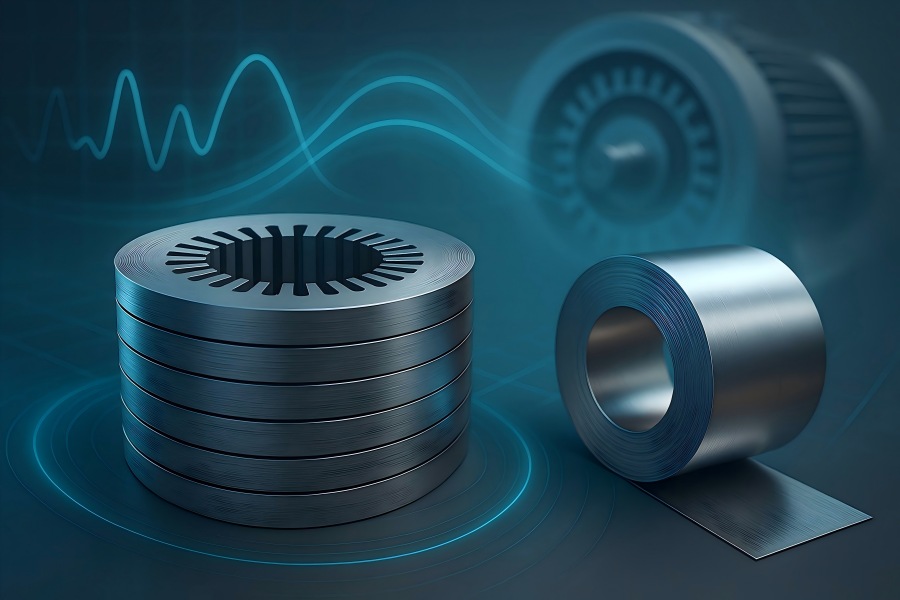
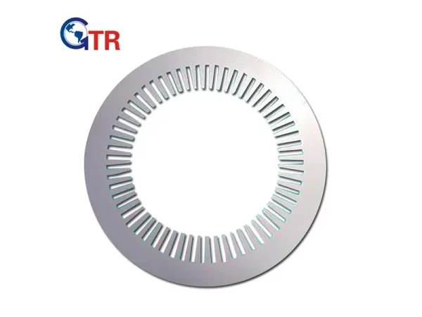
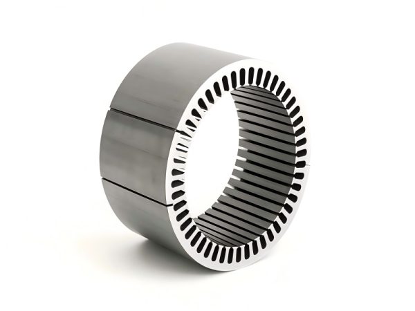
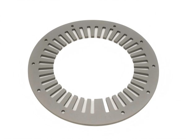
Selecting the right non-oriented electrical steel (NOES) grade is one of the most powerful—and cost-effective—ways to push motor efficiency toward IE4/IE5 targets. Grade choice drives hysteresis and eddy-current losses, magnetizing current, thermal rise, acoustic noise, and even the manufacturing yield of your laminations.
Why grade selection matters
The stator core is a laminated magnetic circuit. Each lamination’s material and thickness set the core’s specific loss (W/kg) at a given flux density and frequency, which in turn determines:
- Efficiency: Less iron loss → less heat → lower total losses → higher η.
- Magnetizing current: Higher permeability and lower coercivity reduce no-load current and copper I²R losses.
- Thermal behavior: Lower core loss reduces operating temperature, extending insulation and bearing life.
- Acoustic noise: Low magnetostriction grades and low loss reduce vibration and audible hum.
- Manufacturability: Strength and coating class affect stamping burrs, die life, inter-laminar insulation, and stack factor.
For stator cores, non-oriented steels (NOES) are used (isotropic properties in-plane). Grain-oriented steels are for transformers and are not suitable for rotating machines due to their anisotropy.
Total core loss Pcore can be represented as:
Pcore = kh * f * Bn + ke * f2 * B2 * t2 + Pexcess
Where:
- f = frequency
- B = peak flux density
- t = lamination thickness
- kh, ke = material constants
- n ≈ 1.6–2.0 (empirical)
- Pexcess = domain wall and anomalous loss term
Implications:
Hysteresis loss scales ≈ f * Bn and depends on coercivity and microstructure (grade).
Eddy-current loss scales ≈ f2 * B2 * t2 and is highly sensitive to thickness t and resistivity.
Grade improvements (e.g., from M470-50A → M300-35A → M235-27A) reduce both hysteresis (cleaner texture, lower Hc) and eddy loss (thinner gauges and higher resistivity), especially at higher frequencies.
Typical electrical steel options for motors
We frequently supply the following representative NOES categories:
Representative NOES properties (typical values at 1.5 T, 50 Hz)
| Grade (thickness) | Core loss P1.5/50 (W/kg) | B50 (T) | Hc (A/m) | Resistivity (µΩ·m) | Yield strength (MPa) | Lamination coating | Cost index* |
| M470-50A (0.50 mm) | 4.7 | 1.70 | 35 | 0.47 | 420 | C3/C5 | 1.00 |
| M300-35A (0.35 mm) | 3.0 | 1.75 | 30 | 0.48 | 480 | C5 | 1.12 |
| M235-27A (0.27 mm) | 2.3 | 1.80 | 28 | 0.50 | 520 | C5/C6 | 1.22 |
* Cost index is relative to M470-50A = 1.00; actual prices vary with market conditions.
Notes:
- Thinner gauges (0.35 mm, 0.27 mm) reduce eddy losses dramatically (∝ t²).
- Higher-Si and cleaner microstructure lower hysteresis loss and magnetostriction.
- Coating class (C3/C5/C6) influences inter-laminar resistance, thermal class, and stack factor.
Frequency sensitivity—why thin gauges win at high speed
At elevated electrical frequency (from higher pole counts or high-speed drives), the eddy-loss term grows with f². Thinner gauges preserve efficiency.
Assume a stator mass of 9 kg, base flux near 1.5 T, and composite frequency scaling P∝f1.5 (practical rule-of-thumb). The following table compares total stator iron loss across grades.
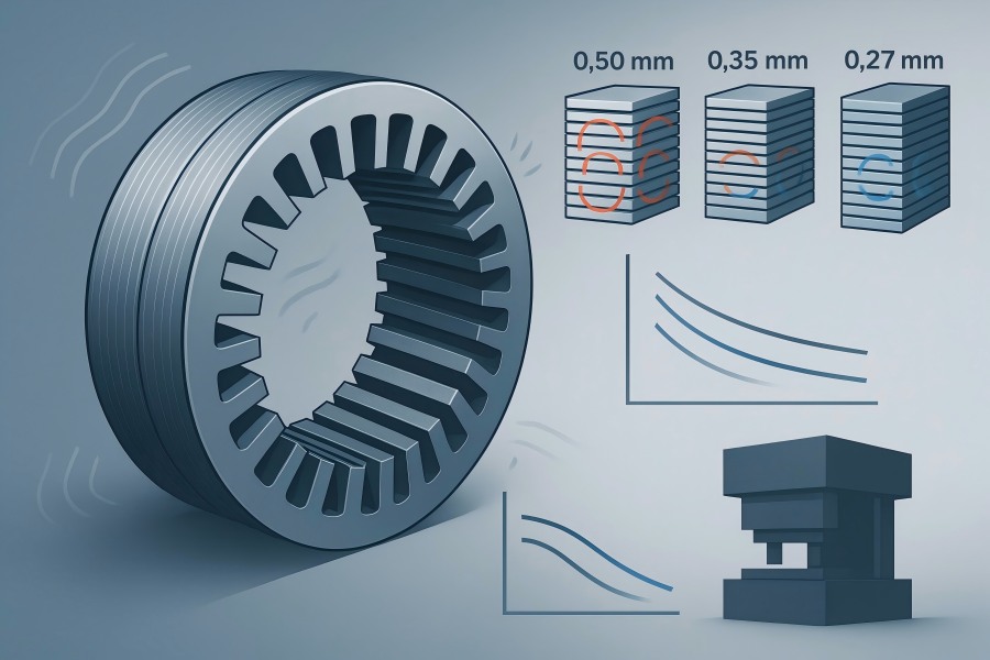
Stator iron loss vs frequency (stator mass 9 kg)
| Frequency | M470-50A (0.50 mm) | M300-35A (0.35 mm) | M235-27A (0.27 mm) |
| 50 Hz | 42.3 W | 27.0 W | 20.7 W |
| 100 Hz | 119.6 W | 76.4 W | 58.5 W |
| 200 Hz | 338.4 W | 216.0 W | 165.6 W |
| 400 Hz | 957.1 W | 610.9 W | 468.4 W |
Result: At 200–400 Hz (typical of high-speed spindles or traction harmonic spectra), upgrading from 0.50 mm to 0.27 mm can cut iron loss by ~50%.
Concrete motor example: 7.5 kW, 4-pole, 50 Hz
Consider a general-purpose 7.5 kW TEFC motor. Keep winding, frame, and rotor constant to isolate stator grade impact.
Assumptions (illustrative):
- Output power Pout =7.5 kW
- Stator mass = 9 kg
- Copper loss (full-load) = 150 W
- Stray load loss = 70 W
- Mechanical (windage+friction) = 30 W
- Core loss = from Table 2 (50 Hz)
Efficiency and heat comparison at 50 Hz
| Grade | Stator iron loss (W) | Other losses (W) | Total loss (W) | Efficiency η |
| M470-50A (0.50 mm) | 42.3 | 250.0 | 292.3 | 96.25% |
| M300-35A (0.35 mm) | 27.0 | 250.0 | 277.0 | 96.44% |
| M235-27A (0.27 mm) | 20.7 | 250.0 | 270.7 | 96.52% |
Interpretation:
Upgrading from M470-50A → M300-35A increases efficiency by about 0.19 percentage points.
Upgrading to M235-27A gains ~0.27 percentage points.
Even small η gains are valuable: they reduce heat, ease thermal design, and often unlock a smaller frame or higher overload capability.
Magnetizing current: Higher-grade NOES typically lowers no-load current by 5–12% in practice for the same flux target, further reducing copper heating (not quantified above to keep comparisons conservative).
Cost–benefit and payback
Let’s estimate annual energy savings for the above 7.5 kW motor running 8,000 h/year at 50 Hz with an electricity tariff of ¥0.8/kWh.
- M470-50A → M300-35A: iron loss reduction = 15.3 W
Annual energy saved ≈ 0.0153 kW × 8,000 h = 122.4 kWh → ¥97.9/year. - M470-50A → M235-27A: iron loss reduction = 21.6 W
Annual energy saved ≈ 0.0216 kW × 8,000 h = 172.8 kWh → ¥138.2/year.
If the material premium is, for example, ¥5/kg for M300-35A and ¥10/kg for M235-27A (stator 9 kg):
- M300-35A: Extra cost ≈ 9 kg × ¥5 = ¥45 → payback ≈ 5–6 months.
- M235-27A: Extra cost ≈ 9 kg × ¥10 = ¥90 → payback ≈ 8–9 months.
Conclusion: For continuously operated motors, upgrading electrical steel often pays back within a year.
Grade choice also affects manufacturing quality
- a) Burr control & die life
Higher-strength, thinner gauges demand sharp tooling but reward you with burrs < 10 µm (with proper die maintenance). Low burrs reduce inter-laminar bridges and thus stray eddy losses. - b) Coating class & stack factor
C5/C6 coatings provide high inter-laminar resistance and thermal stability for VPI/resin impregnation.
Typical stack factor ranges 0.94–0.98, depending on coating thickness and bonding method. A higher stack factor increases effective magnetic length. - c) Stacking method
- Interlock/notch: economical, but place notches away from peak flux paths to limit local loss.
- Bonded stacks (insulation adhesive): excellent damping and low buzz; slightly lower stack factor than press-fitted stacks with thin coatings.
- TIG/laser tack: use sparingly; welding marks should stay in low-flux regions.
- d) Stress management
Stamping induces residual stress that raises loss. We minimize it through:
- Fine-clearance dies and rigid presses.
- Optimized feed direction aligned to strip texture for best isotropy.
- Low-distortion tooling to keep burrs uniform and fiber damage minimal.
- e) Dimensional control
Tight die tolerances preserve slot opening, tooth tip radius, and bridge widths, all of which directly influence air-gap flux, harmonic content, and therefore loss and noise.
Design interactions
A better grade lets you shift design trade-offs:
- Maintain flux density with lower loss → cooler operation at same torque.
- Increase flux density without exceeding thermal limits → higher torque density from the same frame.
- Lower magnetizing current → potentially reduce copper cross-section or temperature rise.
- Reduce acoustic noise when combined with skew, tooth-tip profiling, and slot/pole optimizations.
Because eddy loss ∝ t², thin gauges become especially valuable once slot harmonics or inverter PWM push effective frequency content higher. Pairing thin NOES with skewed rotor/stator, distributed windings, and harmonic-aware tooth geometry compounds the benefit.
Application
| Application | Frequency* | Priority | Recommended thickness | Typical grade band |
| IE3/IE4 industrial motors (pumps, fans) | 50–60 Hz | Efficiency @ rated, cost | 0.35–0.50 mm | M300–M470 family |
| High-speed blowers & spindles | 100–400 Hz | Iron loss @ high f | 0.20–0.27 mm | M235–M270 thin-gauge |
| EV traction & e-axles | 100–1,000 Hz (harmonics) | Low loss + strength | 0.20–0.27 mm | M235 thin-gauge, high-strength |
| Servo motors & robotics | 100–400 Hz | Low loss + low noise | 0.27–0.35 mm | M235–M300 |
| Generators & wind | 50–100 Hz | Efficiency + corrosion | 0.35 mm | M270–M300 |
| Household appliances | 50–60 Hz | Cost | 0.35–0.50 mm | M300–M470 |
* Effective electrical frequency; pole count and drive strategy matter.
Practical checklist for engineers
Define operating spectrum
What is the base frequency? Any VFD? Estimate harmonic content and peak BBB. If frequencies above 100 Hz are significant, prioritize ≤ 0.35 mm, ideally 0.27 mm.
Pick target flux density
Typical motor designs run 1.2–1.6 T in teeth/yoke. Higher BBB boosts torque but magnifies hysteresis and magnetostriction. Match grade to your BBB target.
Set loss budget
Allocate an iron-loss budget (W/kg × kg). Use supplier curves at your BBB and fff (or scale with f1.5f^{1.5}f1.5 if early-stage). Thin grades help stay within budget.
Check mechanical needs
For high RPM assemblies, confirm yield/UTS and consider bonded stacks for damping. Verify skewed stacks remain dimensionally true.
Select coating & stack method
Choose C5/C6 for high inter-laminar resistance and thermal stability. Balance stack factor vs bonding benefits.
Validate with prototypes
We provide laser-cut sample laminations for quick electromagnetic validation and pilot stamping to measure burrs, stack factor, and dimensional stability.
Run the ROI
Compute energy savings from iron-loss reduction, add any copper-loss savings from lower magnetizing current, and compare with material premium. For continuous duty, payback is typically < 1 year.
Noise, vibration, harshness (NVH)
Magnetostriction and residual stress drive NVH. Higher-grade NOES (lower magnetostriction) plus thinner laminations reduce core-borne vibration. Combine grade upgrade with skew (fractional slot), tooth-tip relief, and tight air-gap control for the best acoustic results.
Quality controls we apply
- Incoming coil inspection: thickness, flatness, coating adhesion, P1.5/50, B-H loop sampling.
- Stamping: precision progressive dies, off-press burr meters, and statistical burr control (< 10 µm target on 0.27–0.35 mm strip).
- Stacking: interlock or adhesive bonding with documented stack factor and balance grade.
- Electrical verification: ring sample testing for core loss and permeability per production lot.
- Dimensional: 100% in-process checks for slot width, tooth pitch, OD/ID, and skew angle; CMM sampling on first-off parts.
Putting it all together—recommendation flow
Start with duty profile (continuous/intermittent) and electrical frequency.
Choose thickness to meet the iron-loss budget at that frequency (≤ 0.35 mm above 100 Hz, ≤ 0.27 mm for > 200 Hz).
Refine grade within the chosen thickness to hit your P1.5/50 target while keeping permeability and magnetostriction in check.
Confirm manufacturability (burr, coating, stack method).
Prototype → measure → lock the bill of materials (BOM) and tooling.
Example
- General-purpose IE3/IE4 motor, 2–90 kW: M300-35A provides a robust efficiency uplift at moderate premium, often with sub-year payback in continuous duty.
- High-speed blower/servo: M235-27A enables compact stators with controlled thermal rise and lower NVH.
- Traction auxiliary machines: thin-gauge high-strength NOES keeps losses manageable at PWM harmonics while meeting mechanical demands.

