Electric motors power machines in industries, electric vehicles, and home appliances. At the core of every motor is a carefully engineered magnetic structure that determines efficiency, torque, noise, and reliability. Understanding the stator, rotor, slots, teeth, and back iron reveals how motors perform and why design choices are crucial.
What Are Stator and Rotor?
At their essence, electric motors rely on two main magnetic components: the stator and the rotor. These parts form the magnetic circuit that enables the conversion of electrical power into movement. Although they belong to the same core, the stator and rotor have distinct functions that complement each other.
What Is the Stator?
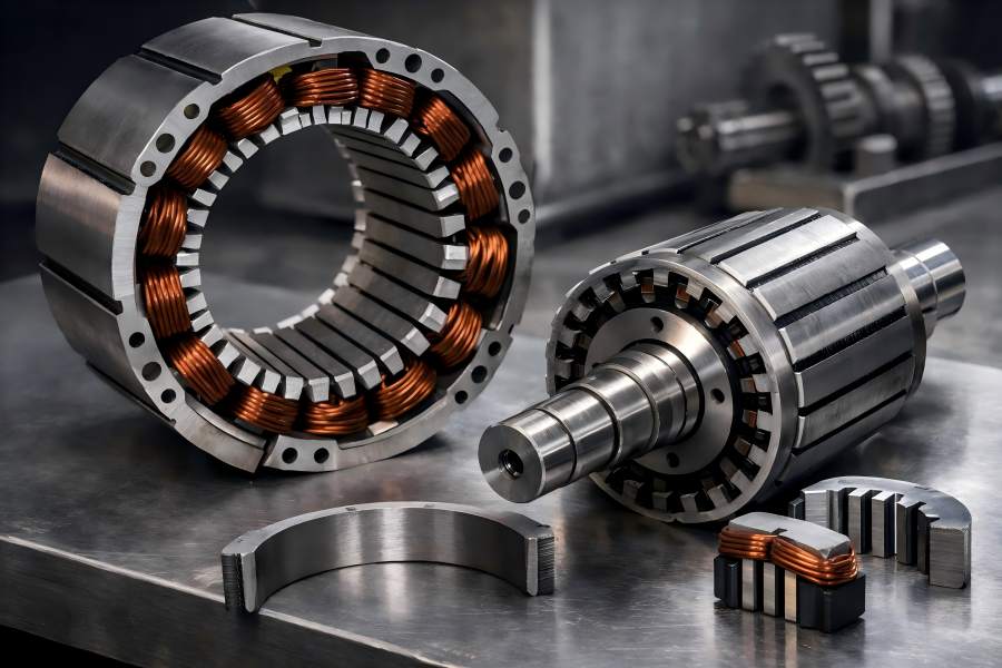
The immobile part of the motor core is called the stator. It is typically built from a stack of thin steel sheets bonded together to form a cylindrical body. This laminated structure reduces electrical losses and keeps the core lightweight while still supporting high magnetic flux levels.
Copper windings are embedded within slots cut into the stator core. A revolving magnetic field is produced when three-phase alternating current is delivered to these windings. This field sweeps around the inside circumference of the motor, forming the primary magnetic force that interacts with the rotor.
From designing windings to selecting lamination materials, the stator is central to controlling the magnetic environment inside a motor. Its configuration affects not only torque production but also electrical efficiency and heat generation.
What Is the Rotor?
The rotor, which is the only component that truly rotates, is nestled inside the stator. The rotor’s job is to respond to the magnetic field of the stator and convert that interaction into rotational motion.
Each type of motor has a different rotor structure. Conductive bars embedded in a laminated core make up the rotor of many industrial motors. These bars form a closed circuit that allows currents to be induced by the stator’s rotating magnetic field, producing torque. In other motor types, permanent magnets may be attached to the rotor surface or embedded within, creating a strong magnetic field without the need for induced currents.
Regardless of configuration, the rotor’s design directly influences how smoothly and efficiently a motor can translate electrical input into mechanical output.
Comparing Stator and Rotor at a Glance
| Feature | Stator | Rotor |
| Motion | Stationary | Rotates |
| Main Role | Creates rotating magnetic field | Produces torque |
| Core Material | Laminated steel | Laminated steel |
| Key Components | Slots, windings | Slots, conductive bars or magnets |
Slots and Teeth
The smooth cylindrical appearance of a motor core conceals a more intricate inner pattern. Both the stator and rotor cores are shaped with alternating ridges and grooves, known respectively as teeth and slots. These features are central to how the magnetic field is shaped and how windings are held in place.
What Are Motor Slots?
Slots are the narrow channels cut into the core that house conductive elements. Copper windings that produce magnetic flux and carry current are housed in slots in the stator. Depending on the type of motor, conductive bars or magnets are located in the rotor’s slots.
These slots’ width, depth, and shape are examples of geometric features that affect motor behavior. For example:
- Slot shape and size affect how much winding material can be placed and how magnetic flux distributes across the air gap.
- Open slots allow easier winding insertion but may result in higher leakage flux and noise.
- Semi-closed or closed slots can improve magnetic performance and reduce acoustic emissions, though they may require more precise manufacturing.
Because slots help determine where and how conductors sit within the core, their design directly impacts torque production, electrical resistance, and thermal dissipation.
Understanding Teeth in the Core
Teeth are the raised portions of the core that separate adjacent slots. They serve as bridges for magnetic flux, guiding it across the air gap between stator and rotor. The width and length of teeth are major design factors:
- Wide teeth can carry higher flux without saturating, enabling stronger torque capabilities.
- Narrow teeth reduce core material usage but can saturate more easily, reducing efficiency.
Teeth also affect acoustic performance. Sudden changes in their geometry can create uneven magnetic forces, leading to vibrations and noise during operation. Engineers often refine tooth shape to balance strong magnetic performance with smoother, quieter motor action.
Slot/Pole Combinations and Their Impact
Motor cores are designed around a concept known as slot/pole ratio, where the number of slots relates to the number of magnetic poles in the machine. This ratio affects:
- Torque smoothness
- Cogging torque (jerky motion at low speed)
- Electrical harmonics
- Manufacturing complexity
Well-chosen slot/pole combinations reduce torque ripple, minimize unwanted vibrations, and improve efficiency, especially in precision applications like robotics or electric vehicle traction motors.
Rotor Slot and Tooth Interaction
While slot and tooth features exist on both stator and rotor cores, their roles differ depending on motor design.
Induction Motor Rotor Design
In a classic induction motor, the rotor contains conductive bars placed in slots that form a “squirrel cage” arrangement. Current is induced in these bars when the rotating magnetic field of the stator passes by. The induced current interacts with the stator’s field, producing torque that spins the rotor.
Key factors here include:
- Bar material and shape: which influence electrical resistance and heat generation.
- Slot dimensions: which affect how easily currents are induced and how torque is developed.
- Teeth geometry: which shapes the path of magnetic flux and alters performance characteristics.
Induction rotors remain one of the most robust and cost-effective designs, balancing reliability with practical performance for countless industrial applications.
Permanent Magnet Rotor Design
Permanent magnet motors use magnets attached to or embedded in the rotor core. These magnets generate their own magnetic fields, eliminating the need for current induction and allowing direct interaction with the stator’s rotating field.
In this configuration:
- Slots may secure magnets or conductors that support the magnet structure.
- Teeth shape and placement influence how flux interacts between magnets and stator windings.
- Magnet quality and placement patterns determine torque density and electrical efficiency.
Permanent magnet motors often achieve higher power density and efficiency than induction counterparts, but require careful thermal and mechanical design to prevent demagnetization and manage heat.
What Is Back Iron?
Behind the slots and teeth lies a thicker steel ring known as back iron or the yoke. It is an essential component of the magnetic circuit in the motor core. Although often overlooked, back iron carries the bulk of the return magnetic flux, completing the loop that begins at the stator windings and crosses the air gap to the rotor.
Why Back Iron Matters
Magnetic flux follows the path of least resistance. After crossing the air gap and traveling through the rotor core, flux must return to the stator via the back iron. Its ability to carry flux efficiently without saturating determines how well the entire magnetic circuit performs.
Design considerations include:
- Thickness of back iron: Too thin can saturate easily; too thick adds unnecessary weight and cost.
- Quality of steel laminations: Influences how much electrical and magnetic loss occurs.
- Mechanical strength: Back iron also helps support the physical structure of the motor core.
Back iron performance affects torque production, efficiency, and heat behavior. If the returning magnetic path is suboptimal, losses increase, reducing overall motor performance.
Performance Effects of Core Geometry
The interplay of motor core elements translates directly into tangible performance outcomes. Here are key areas influenced by stator, rotor, slots, teeth, and back iron design:
Torque and Torque Smoothness
Torque is the rotational force a motor produces. Core geometry affects torque in several ways:
- Slot count and pole arrangements determine how magnetic fields overlap and interact during rotation.
- Teeth geometry affects how evenly flux crosses the air gap, influencing torque ripple and stability.
- Rotor design (induction bars vs. permanent magnets) changes how magnetic energy is converted into motion.
Optimized geometries help produce smooth torque with minimal ripple, critical for applications needing precision and low vibration.
Efficiency and Heat Generation
Electric motors inherently generate heat due to electrical resistance in windings and losses in the core.
Core design affects:
- Eddy current and hysteresis losses: Reduced by laminations and proper material choice.
- Magnetic leakage: Managed by optimized slot and tooth shapes.
- Thermal pathways: Influenced by core geometry that affects heat distribution and dissipation.
Highly efficient cores reduce wasted energy, limiting heat buildup and improving longevity and performance.
Noise and Vibration
Magnetic forces within a motor generate vibrations that may translate into audible noise. Core geometry influences this through:
- Slot/pole interactions: Certain ratios reduce harmonics that cause noise.
- Teeth shape transitions: Smoother flux paths minimize mechanical excitation.
Quiet motor operation is increasingly important in consumer and industrial environments, prompting designers to refine core details.
Design Choices for Different Applications
Motor core design is not one-size-fits-all. Engineers tailor core features to suit performance requirements and operating environments.
Industrial Motors
Industrial applications often demand durability, high torque, and continuous operation. Designs here prioritize:
- Robust induction rotor construction
- Balanced slot and tooth geometry for reliability
- Thicker back iron for flux capacity and structural strength
These motors may sacrifice some compactness for longer life and easier servicing.
Electric Vehicle Motors
Electric vehicle motors focus on efficiency, power density, and smooth performance. These requirements lead to:
- Permanent magnet rotor designs with optimized slot and magnet placement
- Lightweight back iron to reduce vehicle mass
- Advanced tooth and slot patterns for low noise and high torque density
EV motor designers also pay special attention to cooling pathways and thermal management, as high currents and compact cores can increase heat generation.
Precision and Specialty Motors
In robotics, aerospace, and medical devices, motors often require:
- Very low torque ripple
- Minimal vibration and noise
- Tightly controlled thermal behavior
Here, slot/pole combinations and core laminations are fine-tuned for exceptional performance, often at higher manufacturing cost.

