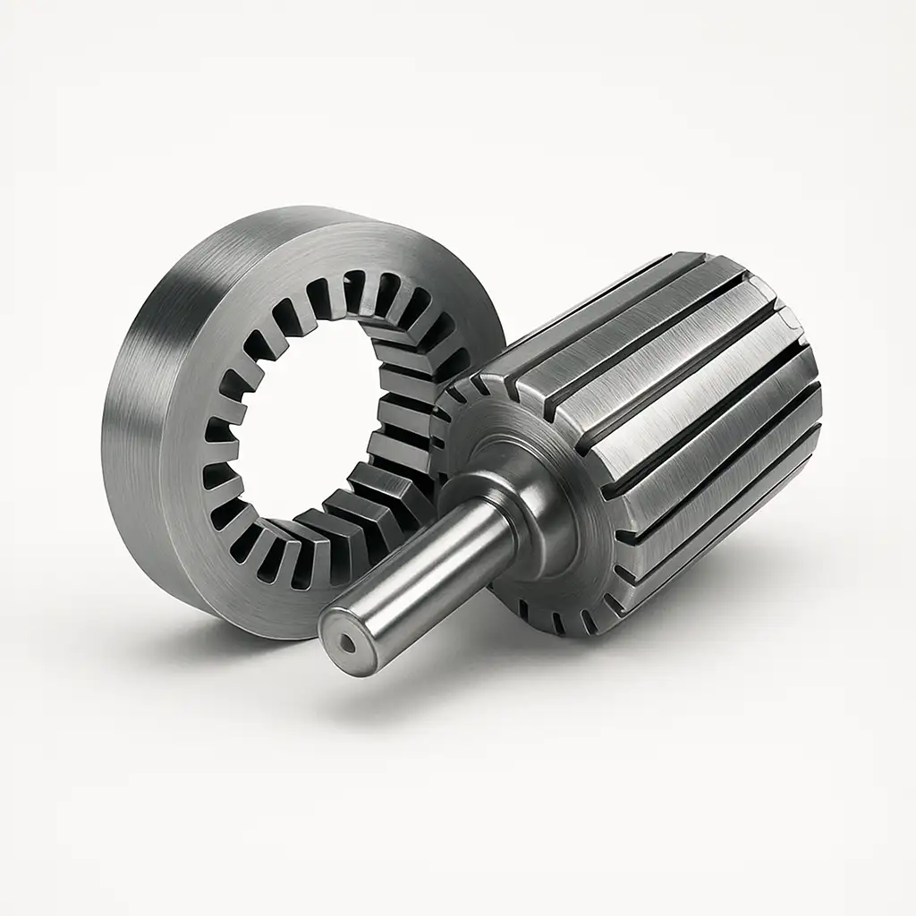
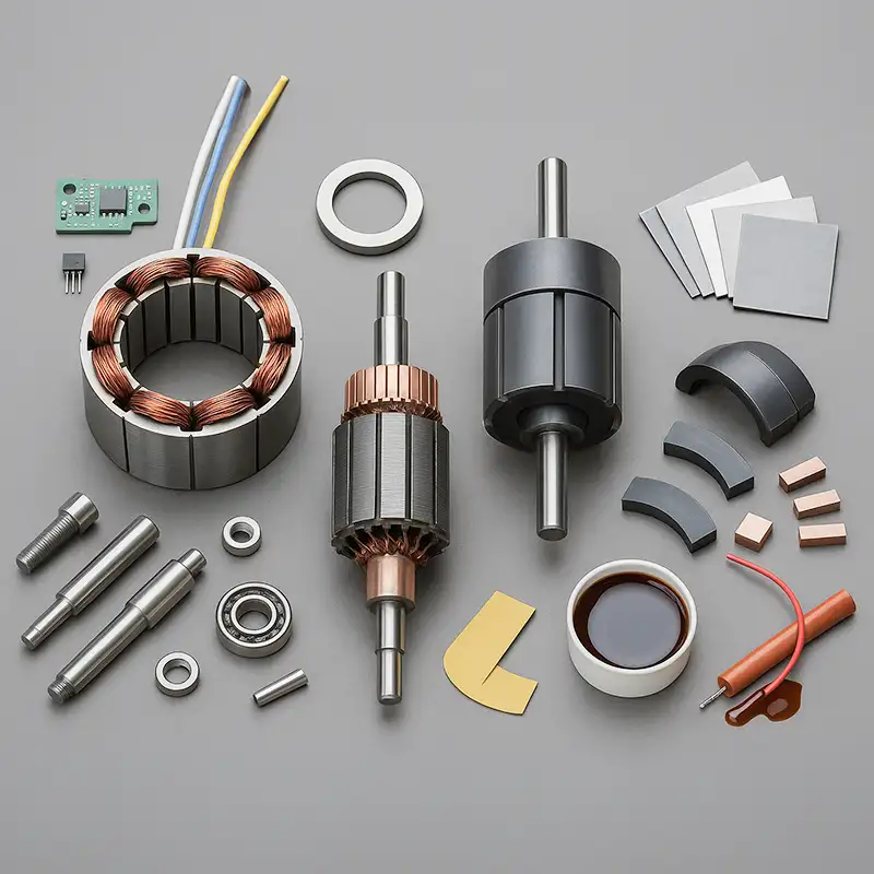
DC Motor Stator and Rotor
- Engineered for torque density and low loss, our DC motor stators and rotors use optimized laminations, precision air-gap concentricity, and ISO 21940 G2.5 balancing.
- We tailor slots, skew, windings, and insulation to boost efficiency, reduce noise, and extend service life.
- Burr Height ≤ 0.02 mm
- Size Coverage: Micro to Large
- RoHS/REACH-Compliant Materials
- IATF 16949 & ISO 9001 Certified
How the DC Motor Stator and Rotor Work Together?
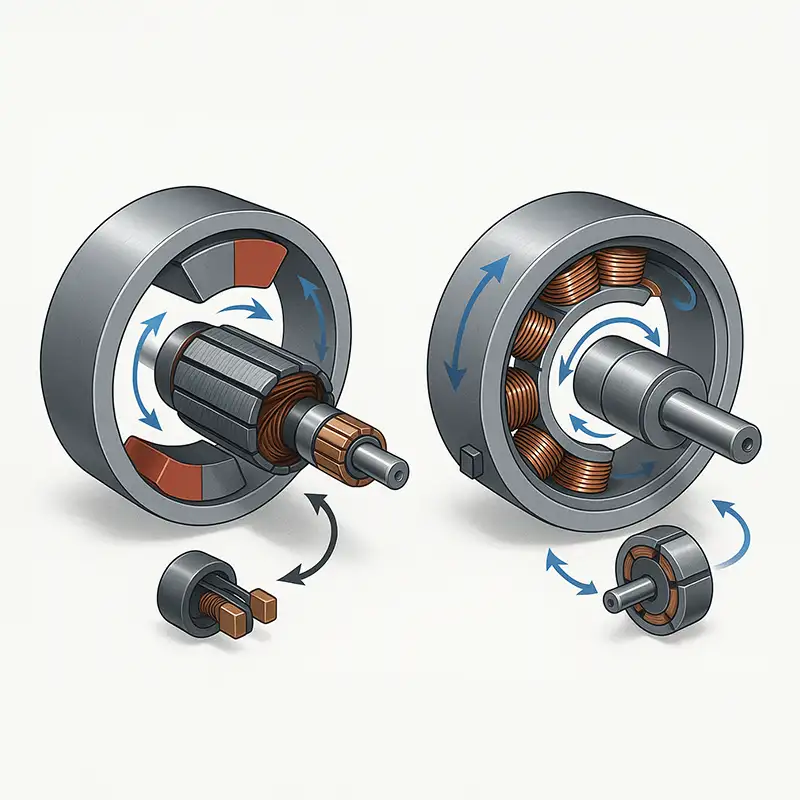
- Torque is produced when the stator’s magnetic field couples across the air-gap with the rotor’s field. Commutation keeps these fields slightly offset so the rotor continually “chases” the rotating stator field.
Brushed DC (PMDC or wound-field)
- Stator: Permanent magnets or field coils create a fixed magnetic field.
- Rotor (armature): Wound coils in slotted laminations. A segmented commutator and brushes switch current in the coils, realigning the rotor field each instant to sustain torque and rotation.
Brushless DC (BLDC)
- Stator: Three-phase windings create a rotating magnetic field.
- Rotor: Permanent magnets. Electronic commutation (via Hall sensors, encoder, or back-EMF) sequences phase currents so the stator field leads the rotor magnets, producing smooth, efficient torque without brushes.
Based on Commutation
We manufacture stators and rotors for brushed and brushless DC motors to meet requirements such as torque, efficiency, noise and durability.
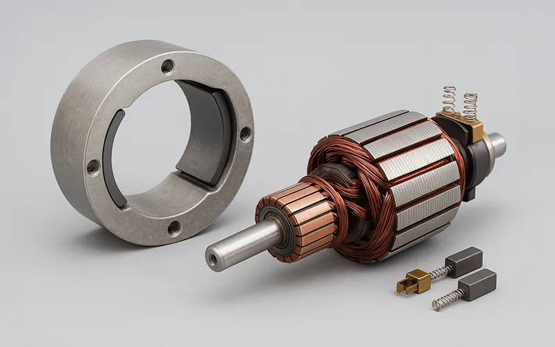
Brushed DC Motor Stator and Rotor
- Laminated stators with magnets or field coils pair with wound armatures, commutators, and brushes, delivering torque, soft starting, simple drives, and reliability.
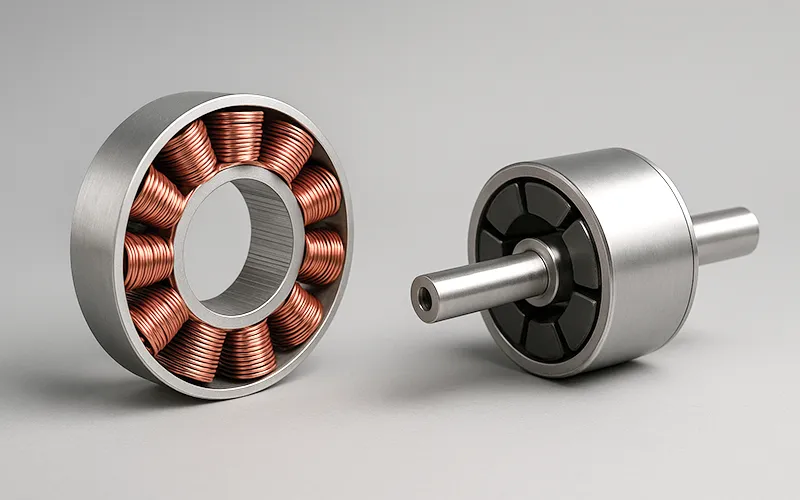
Brushless DC Motor Stator and Rotor
- BLDC Motor Stator and Rotor use electronic commutation with permanent magnet rotors, delivering efficiency, low maintenance, precise control, and wide speed range.
What We Can Customize
- From laminations to finished assemblies, we tailor stators and rotors for torque, efficiency, noise, durability, standards compliance&manufacturability targets.
- Electronic: Sensor placement, commutation strategy, winding configuration, lead routing, and feedback options are tailored to torque ripple, speed, and efficiency targets.
- Mechanical: Stator bores, rotor journals, shaft diameters, keyways, tapers, tolerances, balancing, and runout are controlled for concentricity, vibration, accuracy, and longevity.
- Materials: Lamination grade and thickness, core coatings, commutator bars or magnets, and alloys are selected for loss, strength, cost, and durability.
- Insulation & Finish: Insulation class, VPI or resin systems, liners, lead exits, and coatings are tailored for thermal life, moisture resistance, and standards.
Typical Technical Specifications
Reference ranges and tolerances for DC motor stators and rotors covering materials, geometry, windings, insulation, balancing, testing, and environmental conditions.
Parameter | Range / Options | Notes |
Stator OD | 20–400 mm | One-piece or split yoke; pole-type stators |
Stack height | 5–300 mm | Single or multi-section |
Lamination thickness | 0.20 / 0.35 / 0.50 mm | Others on request |
Steel grades | M235–M400, 50W470, M19 | Low loss / high μ |
Magnet types (PMDC) | NdFeB N35–N52, SmCo, Ferrite | Un-/magnetized delivery |
Rotor slots (typical) | 9–33 | Straight or 0–1 slot-pitch skew |
Air-gap concentricity (TIR) | 0.03–0.08 mm TIR (size-dependent) | With ID/OD datum control |
Rotor runout (journal/OD) | ≤ 0.01–0.03 mm | Pre-/post-impregnation |
Residual unbalance | ISO 21940 G2.5 (certified at 18,000 rpm) | Serialized report |
Insulation class | F / H | Varnish or VPI |
Core loss (guide) | Per steel grade spec (Epstein) | e.g., M235-35A ≤ 2.35 W/kg (50 Hz, 1.5 T); 50W470 ≤ 4.7 W/kg; 60 Hz ≈ 1.2×. |
Stacking factor | ≥ 0.95 | Measured per stack |
Rated speed envelope | Up to 20,000 rpm (size-dependent) | Verify brush surface speed limits |
Traceability | Full serialization-per stator core/stack and per rotor (serialized) | Heat/lot/process history |
Our Manufacturing Process
- We ensure each DC motor stator and rotor meets precise quality standards through advanced engineering, strict inspection, and precision craftsmanship.
- Material Preparation: High-grade silicon steel and copper inspected for purity and consistency.
- Core Stamping: Automated presses punch laminations with minimal burr and tight tolerance.
- Stacking & Bonding: Laminations stacked and bonded to achieve uniform magnetic performance.
- Winding Process: Copper wire precisely wound to ensure electrical balance and insulation strength.
- Insulation Treatment: Coils varnished and baked for superior dielectric and thermal endurance.
- Machining Operations: Shafts, slots, and end faces finished to micron-level dimensional accuracy.
- Dynamic Balancing: Rotating components balanced to minimize vibration and ensure smooth rotation.
- Surface Finishing: Components coated for corrosion protection and long-term performance stability.
- Quality Inspection: Comprehensive electrical, dimensional, and mechanical tests ensure reliability.
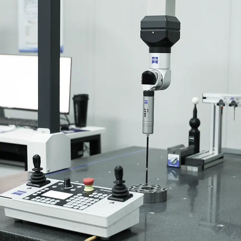
Quality & Testing
- We assure every stator and rotor with documented procedures, calibrated equipment, SPC, and 100% critical electrical and mechanical tests performed.
- Dimensional Control: CMM verifies OD and ID, roundness, concentricity to datums, blue-fit bores, aligned datums ensuring precise air-gap clearance.
- Core Integrity: Lamination count confirmed, burr height ≤0.02 mm audited, interlock welds inspected, stacking factor measured every lot.
- Electrical (when wound): Hi-pot, surge, resistance & inductance tested, commutator bar-to-bar measurements recorded with full traceability/unit.
- Magnetics (PMDC): Magnet grade verified, flux mapping performed, pull-off retention measured, demagnetization margin reviewed against application working point.
- Dynamic Balance: ISO 21940 G2.5 or tighter achieved using single or dual-plane correction, with serialized rotor certificates provided at specified test speed.
- Materials Compliance: RoHS and REACH requirements met, material traceability maintained, mill certificates archived and available for audit review.
- Documentation: PPAP or FAI packages, control plans, travelers, and gauge R&R prepared; records available promptly upon request.
Featured Products
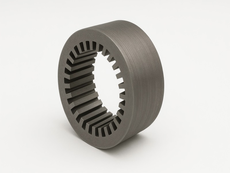
DC Motor Stator Core
- Material: Silicon/Nickel/Cobalt alloys
- Thickness: 0.1–0.5 mm laminations
- Outer Diameter: 30–600 mm range
- Core Type: Yoke, slotted, full ring
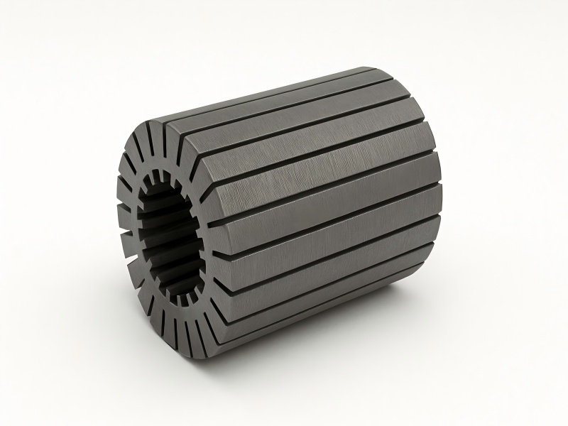
DC Motor Rotor Core
- Material: Silicon steel/iron alloy
- Outer Diameter: 10–200 mm range
- Slot Type: Straight or skewed
- Rotor Type: Wound or PMDC rotor

DC Motor Core
- Stator OD: 50–500 mm
- Rotor OD: 40–400 mm
- Stack Height: Up to 300 mm
- Process: Stamping or laser cutting
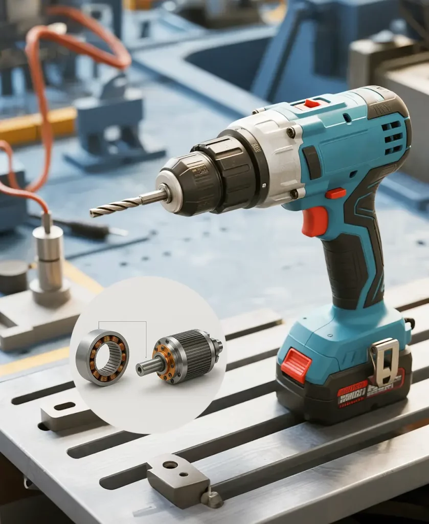
Customer Case
- A handheld power-tool maker needed quieter motors, longer brush life, and cross-plant interchangeability while holding aggressive cost targets.
Our Solution
- Optimized slot geometry and 0.35 mm laminations.
- Added 0.7 slot-pitch skew and tightened ID/OD datum scheme.
- Achieved G2.5 balance at 18,000 rpm and upgraded to Class H varnish.
Results
Metric | Result |
Air-gap concentricity (TIR) | ≤ 0.04 mm |
Residual unbalance | G2.5 achieved @ 18,000 rpm |
Efficiency | +1.3 percentage points vs prior |
Brush life | +22% average |
Acoustic noise | −2.8 dBA at rated load |
First-pass yield | 98.9% over first 5k pcs |
Lead time to SOP | 6 weeks (tooling reused) |
General FAQs
What materials do you use for DC motor stator and rotor cores?
We typically use non-oriented silicon steel laminations, 0.20–0.50 millimeters thick, balancing core loss, saturation, and cost; premium grades also available for high-efficiency applications.
Can DC motor stator laminations be customized for slot geometry and stack height?
Yes, we customize tooth width, slot depth, skew, and stack height to match torque ripple, inductance, limits, and envelope constraints by your application.
Can you supply DC motor rotor with commutators pre-fitted and turned?
Absolutely, armatures are fitted with high-precision commutators, turned and undercut after impregnation; we verify electrical bar-to-bar resistance, runout, and final balance before shipment.
What surface finish options exist for DC motor stator and rotor cores?
Options include phosphate coating, insulation varnish, electrophoretic coating, and anti-rust oiling; each chosen to control interlaminar loss, corrosion resistance, and downstream assembly friction.
Do you manufacture DC motor stator and rotor for harsh environments?
Yes, designs address dust, moisture, and chemicals with sealed varnishes, corrosion-resistant coatings, enhanced creepage distances, and material selections validated by environmental testing standards.

