Electric motors power many of today’s devices and machines—from home appliances to industrial systems and electric cars. Two essential components are at the heart of every motor: the rotor and the stator.
Knowing how these parts work helps engineers, technicians, and manufacturers better understand motor operation, performance factors, and how to improve their use in different industries.
What’s a Stator? The Fixed Core of Power
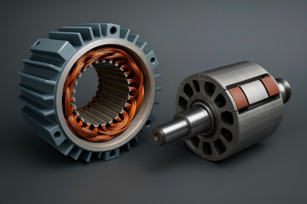
The stator is an electric motor’s stationary part. It provides the framework for the electromagnetic system of the motor. Most stators consist of laminated iron cores and wire windings through which electrical current flows to produce a magnetic field. This magnetic field is crucial—it sets the stage for the rotor to turn and generate mechanical energy.
In AC motors, the stator usually features three-phase windings designed to create a spinning magnetic field when electricity passes through them. Depending on the kind, the stator of a DC motor may contain windings or permanent magnets. The stator’s role is to create consistent magnetic flux, ensuring a stable and efficient electromagnetic interaction with the rotor.
What Is a Rotor? The Spinning Motion Driver
The rotor’s purpose is to revolve, whereas the stator remains fixed. The rotor, which is positioned inside the stator and is supported by a shaft that protrudes outside the motor casing, provides mechanical energy to the load. It rotates due to the torque produced by the interaction between the rotor and the magnetic field produced by the stator.
There are many types of rotors—squirrel cage, wound, permanent magnet—but all serve the same core function: converting electromagnetic energy into mechanical motion. The rotor can carry conductors or permanent magnets and is engineered to respond precisely to the electromagnetic forces generated by the stator.
Key Structural Differences Between Stator and Rotor
The primary structural difference lies in their motion: the stator does not move, while the rotor rotates. But beyond that basic distinction, there are key differences in construction:
- Position: The stator forms the outer part of the motor, while the rotor is located inside it.
- Components: Stators generally include windings and a laminated steel core. Rotors include conductors (bars or windings) and a shaft.
- Function: The stator generates a magnetic field; the rotor turns within that field to produce motion.
- Cooling Needs: Stators typically require more extensive cooling solutions, as the winding losses are a significant source of heat.
These differences influence the motor’s design, maintenance, and performance across applications.
How the Stator and Rotor Work Together
The interaction between stator and rotor is where the magic of electromechanical conversion happens. Rotation is produced by the stator’s magnetic field pulling on permanent magnets in synchronous and brushless DC motors or causing a current to flow through the rotor in induction motors.
The fundamental laws of electromagnetism govern this interaction. For instance, induction motors create their own magnetic field by the induction of currents caused by the relative motion of the rotor and the spinning magnetic field. The torque produced by the two fields interacting causes the rotor to rotate. The rotor and stator magnetic fields lock in, causing synchronous motors to rotate at the same speed.
Without this dynamic electromagnetic interplay, motors would not function. It is this relationship that engineers strive to optimize for improved efficiency, reduced energy loss, and enhanced performance.
Types of Stators Across Motor Designs
Stators vary in construction based on motor type and performance requirements:
- Slotted Stators: Common in AC motors, these have slots where copper windings are placed. They offer excellent magnetic performance but can increase manufacturing complexity.
- Coreless Stators: Often used in compact or high-speed applications like drones and small fans. These eliminate iron losses and reduce weight.
- Segmented Stators: Modular in design, these are easier to manufacture and repair, and allow precise control over the magnetic field.
- Hairpin Winding Stators: Used in automotive traction motors, these offer high power density and superior cooling.
Each stator design reflects a balance between thermal management, manufacturability, magnetic performance, and application needs.
Rotor Variants: From Squirrel Cage to Permanent Magnet
Rotors also come in multiple variants:
- Squirrel Cage Rotor: Made of aluminum or copper bars shorted by end rings. Common in induction motors for their simplicity and ruggedness.
- Wound Rotor: Has windings attached to external resistors and slip rings. gives you control over the torque and speed during startup.
- Permanent Magnet Rotor: Uses magnets embedded or mounted on the rotor surface. High efficiency, commonly used in BLDC and synchronous motors.
- Interior Permanent Magnet (IPM) Rotor: Magnets are embedded within the rotor, improving torque output and field weakening performance.
Rotor design determines torque characteristics, rotational speed, inertia, and control response—all critical for application-specific performance.
Material Choices and Manufacturing Techniques
Material selection and production methods are key to motor performance:
- Laminated Silicon Steel: Used for both stator and rotor cores to reduce eddy current losses.
- Aluminum vs. Copper Windings: Aluminum is lighter and less expensive, while copper has superior conductivity.
- Materials for Magnets: Due to their powerful magnetic capabilities, neodymium and samarium-cobalt magnets are employed.
- Manufacturing Methods: Laser cutting for lamination precision, high-speed stamping for volume production, vacuum pressure impregnation for insulation, and automated coil insertion for consistent winding.
These choices impact cost, durability, and electrical performance.
Performance Impacts: Efficiency, Torque, and Speed
The interaction of stator and rotor influences key performance indicators:
- Efficiency: High-quality lamination and copper windings reduce core and copper losses.
- Torque: Rotor mass and magnet strength determine torque characteristics.
- Speed: The rate of stator magnetic field rotation and rotor inertia define motor speed and response.
Engineers can better design motors for a variety of uses, from electric cars to industrial machines, by knowing these correlations.
Cooling and Heat Management Roles
Electric motors generate significant heat, especially in the stator windings and rotor core. Effective cooling ensures long-term reliability:
Stator Cooling:
- Fan-assisted air cooling
- Liquid cooling systems in high-performance motors
- Integrated heat sinks
Rotor Cooling:
- More complex due to rotation
- Techniques include internal ventilation, hollow shafts, and active cooling in advanced designs
Proper heat dissipation prevents overheating, insulation failure, and efficiency drops.
Applications That Rely on Unique Stator-Rotor Combinations
Motor applications are defined by how the stator and rotor are configured:
- Electric Vehicles: IPM rotors with hairpin stators for high torque and compact packaging.
- Industrial Equipment: Squirrel cage induction motors for durability and simplicity.
- Robotics: Coreless stators and lightweight rotors for fast response and low inertia.
- Consumer Electronics: Flat stators and miniature rotors for silent operation.
- Aerospace: High-efficiency permanent magnet motors with specialized stator geometries.
Each use case demands a tailored design to meet size, weight, efficiency, and performance standards.
Troubleshooting: Common Stator and Rotor Failures
Failures in the stator or rotor can cause motor malfunctions, downtime, or safety hazards:
Stator Issues:
- Insulation breakdown
- Winding shorts or opens
- Overheating from overloading or poor ventilation
Rotor Problems:
- Broken bars in squirrel cage rotors
- Shaft misalignment
- Magnet demagnetization in PM rotors
Preventive maintenance such as thermal imaging, vibration analysis, and electrical testing can detect issues early and reduce costly repairs.

