Electric motors are the beating heart of modern machines, converting electrical energy into mechanical motion with remarkable precision. The two most popular types are brushless DC (BLDC) and brushed DC motors.
Both belong to the DC motor family, but their internal architectures—especially the stator and rotor structures—differ significantly, leading to contrasting performance, maintenance, and application profiles. Understanding how these structural variations affect motor operation is key for engineers and designers seeking the right balance between cost, efficiency, and control.
Fundamental Overview of Brushed and Brushless DC Motors
At their core, both brushed and brushless DC motors rely on the same fundamental electromagnetic principle: a current-carrying conductor placed in a magnetic field experiences a force. Electrical energy can be transformed into mechanical work by rotating as a result of the associated torque.
However, the method of achieving this interaction diverges:
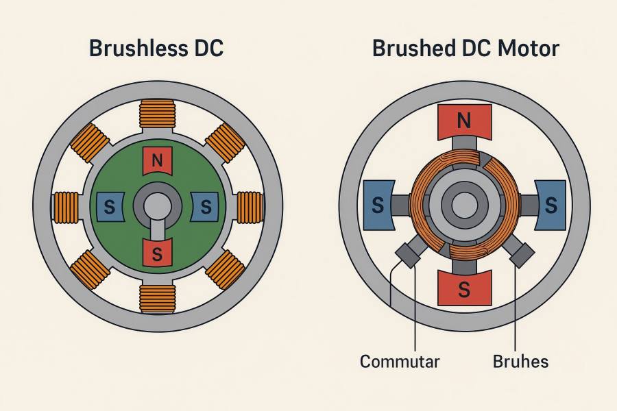
- Brushed DC Motor: Utilizes a mechanical commutator and carbon brushes to periodically reverse current in the rotor windings, ensuring continuous torque in one direction.
- BLDC Motor: Uses an electronic controller for commutation instead of physical brushes. The stator windings are energized sequentially according to rotor position feedback (from sensors or sensorless algorithms).
This replacement of mechanical switching with electronic control redefines how the DC motor stator and rotor are designed and how they interact.
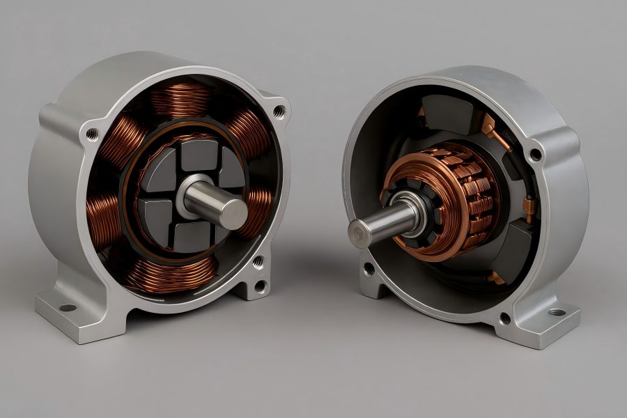
Stator Structure in Brushed DC Motors
In a brushed DC motor, the stator is the stationary magnetic field source. Its primary role is to create a stable magnetic environment for the rotor (armature) to rotate within.
Components and Construction
The stator typically includes:
- Field Windings or Permanent Magnets: Older industrial motors use field windings wrapped around iron pole pieces. Modern small DC motors, such as those in toys or car accessories, use permanent magnets for simplicity and reduced size.
- Magnetic Housing: A steel shell or yoke that completes the magnetic circuit and provides mechanical support.
- Pole Pieces: Shaped iron segments that concentrate magnetic flux and ensure smooth field distribution around the rotor.
Depending on design:
Shunt-Wound DC Motors connect the field winding parallel to the armature for stable speed.
DC in series Because the field winding and armature are connected in series, motors have a high starting torque.
Magnetic Characteristics
The stator’s magnetic flux interacts with the armature’s electromagnetic field to produce torque. Because this field is constant in polarity (north and south poles fixed in space), it’s the rotor current that must be reversed periodically to maintain rotation.
Thermal Behavior
In a brushed DC motor, the stator’s magnetic components (especially electromagnet-based ones) can heat up due to current flow in the field windings. Since these are stationary, cooling is relatively easy, and the structure can be designed for effective heat dissipation through the motor casing.
Rotor Structure in Brushed DC Motors
The revolving part that produces torque through electromagnetic interaction with the stator is called the rotor, or armature.
Armature Core
The rotor’s central part is a laminated steel core, designed to reduce eddy current losses. The core features multiple slots along its circumference, where copper windings are embedded. These windings form coils connected to the commutator segments.
Commutator and Brushes
At one end of the rotor shaft sits the commutator, a cylindrical structure made of copper segments insulated from each other. As the rotor spins, carbon brushes make sliding contact with these segments. To ensure continued rotation, this mechanical switching flips the rotor coils’ current direction every half revolution.
Limitations of the Brushed Rotor
- Friction and Wear: Physical contact between brushes and commutator generates friction, leading to wear, arcing, and occasional electrical noise.
- Maintenance: Brushes must be replaced periodically, especially under high load or continuous use.
- Speed Limitation: At high RPMs, the mechanical commutation becomes unstable, limiting performance.
Advantages
Despite these drawbacks, the rotor’s design allows direct torque control through voltage variation. Brushed DC motors deliver high starting torque and simple control schemes—valuable for low-cost applications like automotive starters or basic actuators.
Stator Structure in Brushless DC Motors (BLDC)
In contrast, the BLDC motor reverses the electromagnetic configuration of its brushed counterpart. The stator becomes the electromagnetically active component, while the rotor carries permanent magnets.
Construction
A typical BLDC stator includes:
- Laminated Steel Core: Composed of stacked silicon steel sheets to reduce eddy currents.
- Winding Slots: Copper windings are embedded in these slots, distributed in patterns (such as star or delta connections) similar to AC motors.
- Coil Phasing: The stator is usually three-phase, though some motors use more poles for smoother torque. Each coil set is energized in sequence according to the rotor’s angular position.
Magnetic Field Generation
Instead of a fixed magnetic field like in brushed motors, the BLDC stator’s field rotates electronically. In order to create torque, the electronic speed controller (ESC) sequentially energizes particular windings, creating a spinning magnetic field that interacts with the rotor’s permanent magnets.
Design Variations
There are two main BLDC stator configurations:
- Inner Rotor Type: The stator surrounds the rotor; most common in industrial and automotive designs.
- Outer Rotor Type: The rotor encases the stator, common in drones and fans, offering higher torque at lower speeds.
Thermal Management
Because the stator windings are fixed to the outer shell, heat dissipation is efficient. The stator’s direct contact with the housing allows designers to integrate cooling fins or liquid channels, improving reliability in high-power or continuous-duty applications.
Rotor Structure in Brushless DC Motors (BLDC)
The rotor in a BLDC motor is simpler than that of a brushed motor, as it contains no windings or commutator.
Core Components
- Permanent Magnets: Usually installed on or immersed within a steel rotor core, these magnets are composed of rare-earth elements like samarium-cobalt (SmCo) or neodymium-iron-boron (NdFeB).
- Rotor Yoke: A ferromagnetic shell that completes the magnetic circuit and mechanically supports the magnets.
- Shaft Assembly: Transmits mechanical output torque to the load.
Magnetic Arrangement
Magnets are arranged around the rotor’s circumference with alternating north and south poles. Depending on the design:
Surface-Mounted Rotors have magnets on the outer surface of the steel core, offering lower torque ripple and easier assembly.
Interior Permanent Magnet Rotors embed magnets inside the core, enabling higher torque density and improved robustness at high speeds.
Magnetic Interaction
As the stator field rotates electronically, the rotor’s permanent magnets align themselves accordingly, ensuring smooth torque generation. The absence of brushes eliminates mechanical friction, allowing higher rotational speeds and greater efficiency.
Rotor Position Sensing
Since there’s no physical commutator, BLDC motors rely on Hall sensors, encoders, or sensorless algorithms to detect rotor position and determine when to switch current among stator phases.
Comparative Analysis: Stator and Rotor Structures
A direct comparison of the stator and rotor design between the two motor types reveals their contrasting philosophies.
| Feature | Brushed DC Motor | Brushless DC Motor (BLDC) |
| Stator Type | Permanent magnets or field windings | Electromagnetic windings (usually 3-phase) |
| Rotor Type | Wound armature with commutator | Permanent magnets |
| Commutation | Mechanical (brushes + commutator) | Electronic (controller + sensors) |
| Friction Source | Brush–commutator contact | Only bearings |
| Maintenance Need | High – brush replacement | Very low |
| Speed Capability | Limited by brush wear | High – limited by bearing load |
| Torque Ripple | Moderate | Can be minimized with control algorithms |
| Cooling Efficiency | Good (stator or field windings easily cooled) | Excellent (stator is outer shell) |
| Manufacturing Cost | Low | Higher (magnets + electronics) |
| Applications | Toys, starter motors, actuators | EVs, drones, CNC machines, robotics |
Material and Magnetic Considerations
Rotor Materials
Brushed DC: Laminated iron core and copper windings—heavier, higher losses due to I²R heating.
BLDC: Permanent magnets reduce copper losses, lighter and more compact.
Stator Materials
Brushed DC: Often includes ferromagnetic pole pieces with wound coils or magnets.
BLDC: Laminated stator steel with precision-machined slots ensures balanced magnetic flux and low eddy losses.
Magnetic Efficiency
In BLDC motors, permanent magnets provide a constant magnetic field, reducing excitation losses. Brushed motors consume part of their input power to generate the stator field (in wound-field versions), reducing overall efficiency.
Influence on Motor Performance
Efficiency
BLDC motors typically achieve 85–90% efficiency, while brushed motors often remain around 75–80%, due to frictional and commutation losses.
Torque Characteristics
Brushed Motors: Offer high initial torque, suitable for applications like cranes or traction.
BLDC Motors: Provide smoother torque over a wider speed range, ideal for precision control.
Speed Range
BLDC motors excel at high-speed performance—tens of thousands of RPM—because there’s no mechanical commutator. Brushed motors, by contrast, risk brush bounce or arcing at elevated speeds.
Noise and Vibration
The absence of mechanical contacts makes BLDC motors quieter and smoother, important for applications like drones, medical devices, and electric vehicles.
Cooling and Reliability Considerations
Heat Distribution
In brushed motors, heat concentrates in the rotor (due to copper losses), which is harder to cool because it rotates. In BLDC motors, heat is generated mainly in the stator, which is stationary and thus easily cooled—contributing to better thermal stability and longer lifespan.
Bearing Load and Balance
Because BLDC motors rotate faster and have lighter rotors, they require precise dynamic balancing. However, absence of brush friction means bearings last longer.
Maintenance
Brushed motors demand regular inspection and replacement of brushes, especially in continuous or dusty environments. BLDC motors, having no contact wear, can run for tens of thousands of hours without service.
Design Evolution and Industrial Adoption
From Brushed to Brushless
The transition from brushed to brushless designs mirrors the broader industrial shift toward efficiency, digital control, and reduced maintenance. BLDC motors’ reliance on electronic commutation dovetails with advancements in microcontrollers and power electronics.
Application Differentiation
- Brushed DC Motors: Remain valuable in simple, low-cost systems—like car wipers, toys, and small appliances—where control complexity isn’t justified.
- BLDC Motors: Dominate high-efficiency, precision, or variable-speed sectors—such as electric vehicles, aerospace, HVAC fans, CNC spindles, and robotics.
Engineering Trade-offs
The superior efficiency and durability of BLDC motors come at higher upfront cost and complexity. However, lifecycle economics often favor BLDCs due to lower energy consumption and minimal servicing.
Stator and Rotor Dynamics in Motion Control
Electromagnetic Torque Generation
Both motor types rely on the torque equation:
T=kt×I
where T is torque, kt is the torque constant, and III is armature current. However, the field interaction mechanism differs—brushed motors rely on physical current reversal, while BLDC motors synchronize current electronically.
Field Orientation
In brushed motors, torque smoothness depends on commutator segmentation.
In BLDC motors, torque ripple depends on phase switching precision and magnet geometry.
Control Precision
BLDC stator control allows for field-oriented control (FOC) or trapezoidal control, providing fine-tuned torque and speed regulation—unachievable in traditional brushed designs without external sensors or feedback systems.

