Modern industries—from robotics and automation to electric vehicles and aerospace—rely on electric motors that deliver high precision, speed, and energy efficiency. Among these, Brushless DC (BLDC) and servo motors have emerged as key technologies for motion control systems that demand accuracy, torque stability, and dynamic responsiveness.
Yet behind the sleek housing of these motors lies a crucial component that defines their performance: the rotor. In recent years, customized rotor designs have become one of the most powerful ways to optimize motor behavior, enabling manufacturers to fine-tune speed, torque, inertia, and efficiency to specific application requirements.
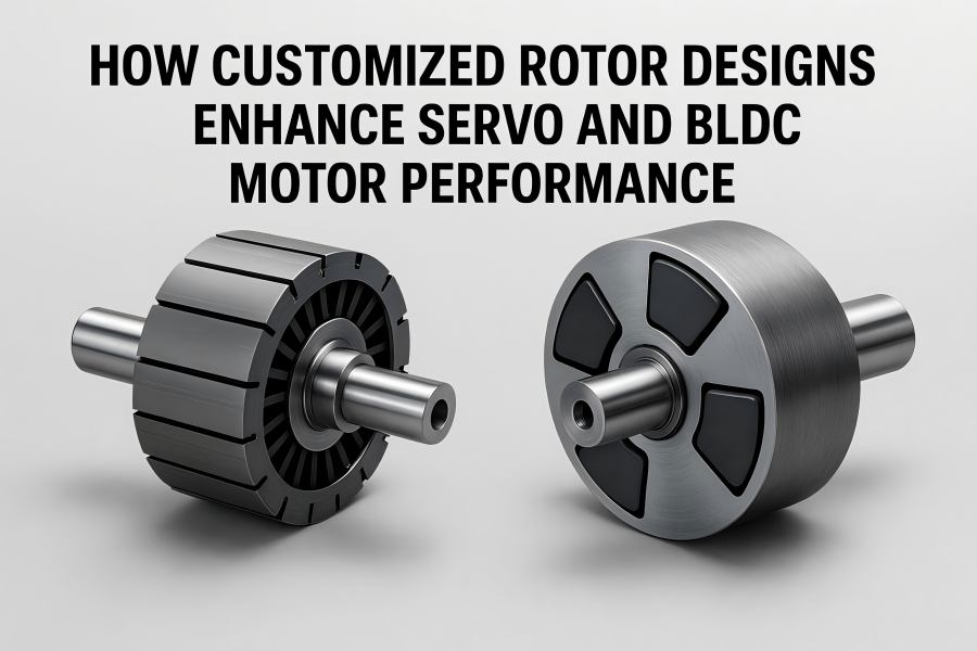
Understanding the Role of the Rotor in Motor Operation
The revolving component of an electric motor that produces torque by interacting with the magnetic field of the stator is called the rotor. In BLDC and servo motors, it typically contains permanent magnets, laminated steel cores, and sometimes embedded features like cooling channels or balance slots. The way the rotor is shaped, magnetized, and assembled directly influences key performance metrics
such as:
- Torque output and ripple
- Rotational inertia
- Thermal stability
- Magnetic flux distribution
- Noise and vibration levels
While the stator’s winding design determines how electromagnetic fields are generated, it is the rotor that translates this field into mechanical motion. Therefore, customizing rotor geometry, magnet arrangement, and material composition allows engineers to fine-tune how effectively this conversion happens.
Key Differences Between Servo and BLDC Motor Rotors
Although both servo and BLDC motors share similar principles, their rotor designs serve different operational goals.
Servo Motor Rotors
Servo motors are engineered for precision control—accurate positioning, minimal overshoot, and high dynamic response. In order to facilitate quick acceleration and deceleration, their rotors are usually tuned for low inertia. They often use high-energy rare-earth magnets (such as NdFeB) and finely balanced shafts to reduce vibration. In many cases, servo rotors are designed for smooth torque profiles and integrated feedback systems (e.g., encoders or resolvers).
BLDC Motor Rotors
BLDC motors are designed for high efficiency and continuous operation with minimal maintenance. Their rotors generally feature surface-mounted or interior permanent magnets, depending on the desired torque-speed characteristics. Surface-mounted rotors offer simplicity and low cogging torque, while interior permanent magnet (IPM) designs enhance torque density and field weakening capability.
Customization in BLDC rotors often revolves around magnet shape, pole count, and flux concentration, allowing manufacturers to tailor motors for applications like drones, compressors, and electric power tools.
Benefits of Customized Rotor Design
Customizing rotor design provides substantial benefits that standard designs cannot achieve. Below are some of the most significant performance gains.
Increased Density of Torque
In high-power, compact applications, torque density—the quantity of torque produced per unit volume—is a crucial parameter. By adjusting the magnet arrangement (surface-mounted, buried, or hybrid configurations) and optimizing the air gap geometry, designers can increase magnetic flux linkage between stator and rotor. This allows the motor to deliver higher torque without increasing size or weight.
For instance, IPM rotors with V-shaped magnet slots can improve torque production by 10–25% compared to surface-mounted types while maintaining structural rigidity.
Reduced Cogging Torque
Cogging torque—an unwanted jerking motion due to interaction between stator slots and rotor magnets—affects smoothness and noise in precision applications like CNC machines or camera gimbals. Customized rotor solutions, such as skewed magnet alignment or optimized pole arc ratios, can minimize cogging by balancing the magnetic field distribution. This yields smoother motion and quieter operation, essential for servo systems demanding sub-degree positioning accuracy.
Improved Dynamic Response
Servo motors must accelerate, stop, and reverse direction rapidly. By designing rotors with reduced inertia, engineers improve acceleration rates and control stability. Customization might include using hollow shafts, lightweight aluminum or carbon-fiber sleeves, and compact magnet placement to cut mass without sacrificing torque strength. This directly translates to faster system responsiveness in robotic arms, pick-and-place machines, and motion platforms.
Optimized Thermal Management
Heat accumulation is a major factor limiting motor lifespan and efficiency. Custom rotor designs may integrate embedded cooling ducts, ventilation holes, or heat-conductive bonding materials to improve thermal dissipation. Lower operating temperatures preserve magnet integrity and reduce the risk of demagnetization. Some advanced designs even use liquid-cooled shafts or high-conductivity sleeves for motors in continuous-duty industrial environments.
Reduced Vibration and Acoustic Noise
Vibration and noise not only degrade mechanical stability but also signal inefficiencies in electromagnetic conversion. Custom balancing, precision rotor machining, and magnet skewing can reduce harmonic noise caused by torque ripple or eccentricity. This benefit is particularly valuable in medical equipment and laboratory automation, where acoustic quietness and minimal vibration are crucial.
Design Parameters for Rotor Customization
Rotor customization involves multiple interacting design variables. Optimizing these requires a deep understanding of both electromagnetic theory and mechanical engineering principles.
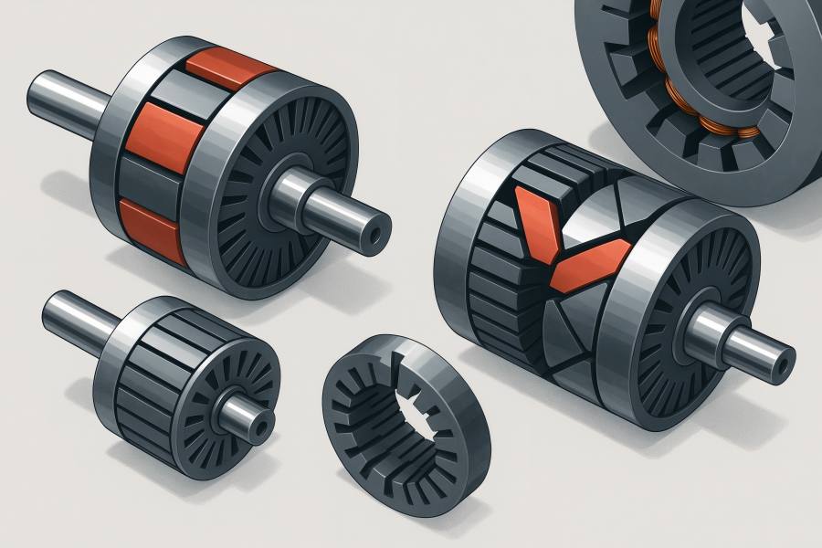
Magnet Configuration
- Surface-Mounted Magnets (SPM): Simple to manufacture, ideal for constant-speed BLDC motors. Customization often focuses on magnet thickness, pole arc ratio, and adhesive bonding to minimize eddy losses.
- Interior Permanent Magnets (IPM): Embedded magnets offer superior field weakening and torque density. V-shaped, U-shaped, or radial interior arrangements allow engineers to fine-tune performance curves for wide speed ranges.
- Hybrid Designs: Combining surface and buried magnets yields both high torque and high efficiency, suitable for electric vehicles or precision servo systems.
Rotor Core Geometry
The core is usually made of laminated silicon steel to minimize eddy currents. Customizing the lamination shape or slot distribution helps control flux leakage and torque ripple. Thinner laminations reduce core losses but increase cost and complexity.
Material Selection
Rotor materials must balance magnetic permeability, strength, and cost:
- Silicon Steel (Fe-Si): Standard material for rotors due to low core loss and good magnetic properties.
- Cobalt-Iron Alloys: Used in high-performance servo motors for elevated flux density and temperature resistance.
- Carbon Fiber or Aluminum Sleeves: Reduce mass and provide mechanical containment for high-speed rotors.
Air Gap Optimization
The air gap—the small clearance between stator and rotor—directly influences magnetic coupling and efficiency. A customized rotor design allows engineers to minimize air gap irregularities, achieving consistent torque and smoother operation. In high-speed BLDC motors, uniform air gaps prevent mechanical imbalance and reduce noise.
Rotor Balancing and Tolerances
High-speed rotors must be precisely balanced to prevent vibration-induced wear. Custom designs often include dynamic balancing holes, end-ring adjustments, and precision grinding. The tighter the tolerance, the lower the noise and the longer the bearing life.
Simulation and Optimization Tools for Rotor Design
The era of digital engineering has revolutionized how rotor designs are customized. Engineers now use finite element analysis (FEA) and computational fluid dynamics (CFD) tools to simulate performance before production.
Electromagnetic Simulation
FEA software allows precise modeling of magnetic field distribution, torque ripple, and back-EMF profiles. By testing variations in magnet placement, pole count, or rotor shape, designers can find optimal configurations that deliver target torque-speed curves.
Thermal Simulation
Thermal mapping identifies hotspots and evaluates cooling efficiency under real load conditions. This enables the integration of temperature-resistant materials or improved ventilation without multiple physical prototypes.
Structural and Vibration Analysis
Mechanical simulations assess stresses under high-speed rotation, helping prevent shaft deflection, cracking, or imbalance. Combined with vibration modal analysis, they guide adjustments in magnet bonding and rotor lamination thickness.
Multi-Objective Optimization
Today’s design process often uses AI-assisted algorithms to optimize several goals simultaneously—such as maximizing torque while minimizing losses and weight. This leads to unique rotor geometries that outperform conventional designs.
Application-Specific Customization Strategies
Rotor customization is rarely one-size-fits-all. Instead, it is tailored to the operational environment and control requirements of specific industries.
Robotics and Automation
Servo rotors in robotic joints prioritize lightweight and low-inertia construction. Customizations like thin laminations, hollow shafts, and optimized pole pairs enable fast acceleration and deceleration cycles. High-resolution feedback encoders further refine position control.
Electric Vehicles (EVs)
BLDC and IPM rotors in EV traction motors emphasize high torque density and field weakening capability for wide-speed operation. Custom cooling channels and reinforced rotor sleeves allow sustained high-speed rotation, while specialized magnet retention systems prevent demagnetization at high temperatures.
Aerospace and Drones
In aerospace and UAVs, rotor customization focuses on weight reduction and balance precision. Carbon-fiber sleeves, skewed pole structures, and high-strength magnet adhesives ensure reliability under extreme vibration and temperature conditions.
Industrial Automation
Factory servo drives require constant torque at variable speeds. Custom rotor designs reduce cogging torque and heat buildup, enabling 24/7 operation. Integrating additional inertia rings can stabilize motion in conveyor and packaging systems.
HVAC and Compressors
In BLDC compressors, rotors are tailored for smooth low-speed operation and efficient partial-load performance. Magnet segmentation and optimized flux paths reduce harmonics and energy waste during variable load cycles.
Case Study: Interior Permanent Magnet Rotor for High-Speed Servo Drive
A major manufacturer of industrial robotics sought to enhance the acceleration capability of its servo motors while maintaining torque output. Engineers developed a custom IPM rotor with buried NdFeB magnets arranged in a double V-shape. FEA simulations predicted a 20% torque improvement and 15% reduction in rotor inertia.
To address mechanical stress at 12,000 rpm, a carbon-fiber sleeve was added for structural reinforcement, allowing thinner laminations and lower mass. Testing confirmed faster response times, smoother speed transitions, and reduced temperature rise—demonstrating how targeted rotor customization directly enhances servo performance metrics.
Manufacturing Techniques for Customized Rotors
Advanced rotor designs require precision manufacturing to translate digital concepts into real-world reliability.
Precision Machining
CNC milling and grinding ensure that shaft diameters, magnet slots, and balance holes meet micrometer-level tolerances. This precision is vital to prevent eccentricity and vibration during high-speed operation.
Magnet Insertion and Bonding
Customized rotors often use laser alignment for accurate magnet placement. High-temperature adhesives or mechanical interlocks ensure that magnets remain secure under centrifugal forces.
Rotor Assembly Balancing
Dynamic balancing systems measure vibration amplitude and apply counterweights or hole drilling to achieve symmetrical mass distribution. Automated systems verify balance for each rotor, guaranteeing consistency in batch production.
Heat Treatment and Coating
To resist corrosion and fatigue, rotor cores may undergo vacuum heat treatment and anti-rust coating. Coatings also serve as insulation layers to prevent short-circuiting between laminations.
Quality Control and Testing
Each custom rotor undergoes torque ripple testing, back-EMF validation, and thermal cycling tests. Manufacturers employ laser scanning and eddy current inspections to detect cracks or misalignments before final assembly.
Material Innovations Driving Rotor Customization
The next generation of rotors benefits from ongoing material research and hybrid engineering approaches.
- High-Coercivity Magnets: New NdFeB formulations resist demagnetization even at 200°C, extending the operational range of servo motors.
- Amorphous Metal Laminations: Offering ultra-low core losses, these enable higher efficiency at elevated frequencies.
- Composite Rotor Sleeves: Carbon and aramid fibers provide strength with minimal weight, ideal for high-speed or airborne motors.
- Additive Manufacturing: 3D printing of rotor components allows complex geometries and integrated cooling paths previously impossible through machining.
Material advances not only enhance performance but also reduce dependency on rare earth elements through improved magnetic circuit efficiency.
Integration with Control Algorithms
A customized rotor design reaches its full potential only when paired with optimized control algorithms. Servo and BLDC controllers use feedback from position sensors to adjust current flow and maintain desired torque and speed. When rotor characteristics—such as back-EMF waveform or inertia—are known precisely, control parameters like commutation timing, PID gains, and flux weakening settings can be fine-tuned.
This synergy between hardware customization and software optimization results in motors that respond more predictably, waste less energy, and operate more quietly. In modern Industry 4.0 systems, digital twins simulate both the rotor and control logic to continuously refine performance.
Economic and Operational Advantages
Though customized rotor development involves higher upfront engineering costs, it provides long-term value in several ways:
- Higher efficiency lowers power consumption and operational costs.
- Extended service life reduces maintenance frequency.
- Better torque-to-weight ratio enables smaller, lighter equipment.
- Faster dynamic response increases productivity in automation lines.
- Improved reliability reduces downtime and warranty claims.
In high-volume applications such as EVs or robotic arms, these advantages quickly offset initial development expenses.
The Future of Rotor Customization
As industries pursue greater electrification and automation, the customization of motor rotors will continue to evolve. Future trends include:
Digital twin–driven optimization, where virtual models test thousands of rotor variants before manufacturing.
Real-time temperature, vibration, and magnetic flux monitoring is possible with smart rotors that have embedded sensors.
Sustainable design approaches, such as recyclable magnet materials and modular rotor assemblies.
Integrated motor-drive systems, where rotor design and control electronics are co-optimized for peak efficiency.

