Electric motors are the heartbeat of modern industry. They power everything from household fans to high-speed trains, from compact drones to large-scale manufacturing lines. Any electric motor’s dynamic pair at its core are the stator and rotor.
Although these two parts cooperate to transform electrical energy into mechanical motion, their materials, structures, functions, and performance traits are very different. For engineers, producers, and users looking to maximize cost, efficiency, and dependability across motor applications, it is imperative that they comprehend these distinctions.
Overview of Electric Motor Operation
To appreciate the distinctions between the stator and the rotor, it helps to recall how an electric motor works. An electric motor uses the interaction of current-carrying conductors and magnetic fields to transform electrical energy into mechanical torque.
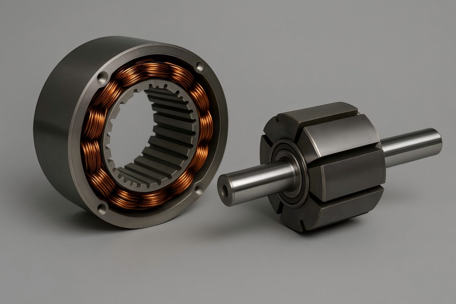
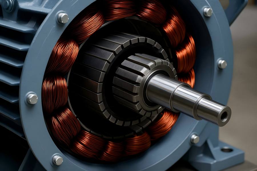
A magnetic field is produced by the stator, which is the stationary component, either by electromagnetic windings or permanent magnets. The rotor, positioned inside the stator and mounted on the motor shaft, rotates when magnetic forces act upon it. Together, these two components form the fundamental electromechanical energy conversion system.
Depending on the type of motor—AC or DC, synchronous or asynchronous, brushed or brushless—the design and working relationship between stator and rotor may vary significantly. However, their core functions remain consistent: the stator generates or channels magnetic flux, while the rotor converts that flux into motion.
Key Differences
| Category | Stator | Rotor |
| Function | Generates magnetic field | Converts magnetic field into motion |
| Motion State | Stationary | Rotating |
| Connection to Power | Direct | Indirect (induced or magnetic) |
| Heat Source | Copper and core losses | Induction and mechanical friction |
| Cooling Method | Fixed fans or water jackets | Shaft airflow or internal channels |
| Failure Risks | Insulation aging | Bearing failure, imbalance |
| Maintenance | Electrical | Mechanical |
| Innovation Focus | Coil design, cooling, insulation | Magnet integration, dynamic balance |
| Impact on Motor Performance | Efficiency, flux strength | Torque, speed, inertia |
Definition and Role of the Stator
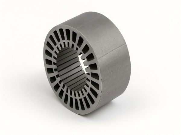
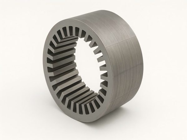
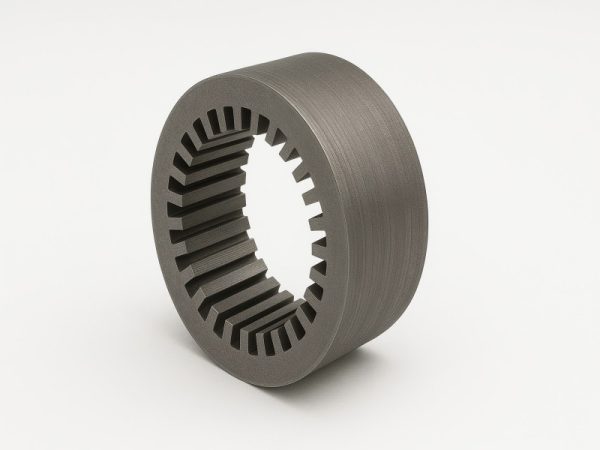
The stationary outer part of an electric motor is called the stator. It typically consists of a laminated steel core, slots for windings or magnets, and a frame that supports mechanical structure and heat dissipation.
Functions of the Stator:
- Magnetic Field Generation: The stator creates a rotating magnetic field (in AC motors) or a static field (in DC motors) that interacts with the rotor.
- Structural Support: It houses the rotor, bearings, and sometimes the cooling system, maintaining alignment and mechanical stability.
- Electrical Insulation and Safety: To avoid short circuits and guarantee safe operation at high temperatures or voltages, the stator windings are insulated.
In short, the stator is the “source” of the magnetic environment in which the rotor moves. Without a properly designed stator, the motor’s efficiency, torque output, and heat management all suffer.
Definition and Role of the Rotor
The electric motor’s revolving part is called the rotor. It transfers mechanical energy to the load by being coupled to the output shaft. The rotor’s design determines how effectively it can convert magnetic flux from the stator into motion.
Functions of the Rotor:
- Electromechanical Conversion: The rotor turns magnetic energy into mechanical torque.
- Current Induction (in AC motors): In induction motors, current is induced in the rotor bars or coils due to electromagnetic induction from the stator.
- Mechanical Output: The rotor transmits rotational energy through the shaft to perform useful work.
In many designs, the rotor’s performance characteristics—such as inertia, resistance, and magnetic permeability—are tailored to specific applications, from high-speed turbines to heavy-duty cranes.
Structural Composition and Materials
Stator Materials and Construction
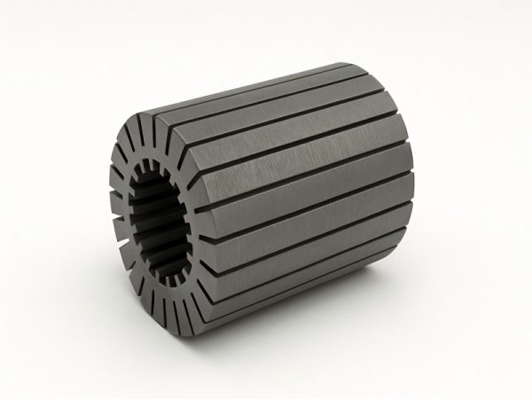
Electrical steel sheets that are thin and laminated are typically used to make the stator core. The lamination minimizes eddy current losses by reducing circulating currents within the metal. Copper or aluminum windings are inserted into the stator slots, insulated with varnish or epoxy. The frame is typically cast iron, aluminum, or steel, providing mechanical rigidity and efficient heat transfer.
High-performance motors often feature slotless stators or distributed windings, which enhance magnetic efficiency and reduce cogging torque. Cooling channels or external fans may also be integrated for thermal management.
Rotor Materials and Construction
The rotor’s construction varies depending on motor type:
- Squirrel-Cage Rotor (Induction Motors): The most common design features aluminum or copper bars embedded in a laminated steel core, short-circuited by end rings.
- Wound Rotor (Slip-Ring Motors): Contains insulated copper windings connected to slip rings, allowing external resistance control.
- Permanent Magnet Rotor (Brushless Motors): Incorporates rare-earth magnets (such as neodymium or ferrite) to produce strong magnetic fields without induced current losses.
Additionally, rotor laminations are insulated to reduce eddy currents. The shaft, typically made of high-strength steel, supports rotation and torque transmission.
Working Principle Differences
While both stator and rotor participate in electromagnetic energy conversion, their operating principles differ:
Stator Action: When alternating current flows through stator windings, it produces a rotating magnetic field. In DC motors, the stator generates a stationary magnetic field that interacts with the rotating armature (rotor).
Rotor Reaction: The rotor responds to the stator’s field by either:
- Inducing current (in induction motors), producing torque due to Lorentz forces.
- Aligning with the field (in synchronous motors), rotating in step with the magnetic flux.
- Reacting to permanent magnets (in BLDC or PMSM motors), yielding highly efficient motion without slip.
The interplay between stator field and rotor motion defines key performance metrics such as torque, speed, and efficiency.
Magnetic Field Interaction
The magnetic field interaction between the stator and rotor is the most important physical process.
- When an AC induction motor is used, A synchronously spinning magnetic field is produced by the stator.
- The rotor, initially stationary, experiences a changing magnetic flux.
- This induces current in the rotor bars, creating a magnetic field that interacts with the stator field.
- The resulting electromagnetic torque accelerates the rotor until it approaches, but never reaches, synchronous speed.
In synchronous or brushless DC motors:
- The rotor’s magnetic poles (either from magnets or DC excitation) lock onto the stator’s rotating field.
- The rotor and stator fields remain synchronized, eliminating slip and providing precise speed control.
This electromagnetic coupling is where the “static” and “rotating” names originate—and where the distinction between stator and rotor becomes functionally essential.
Electrical and Mechanical Differences
| Aspect | Stator | Rotor |
| Position | Stationary, outer section | Rotating, inner section |
| Function | Generates magnetic field | Converts field into motion |
| Motion | Fixed, no rotation | Spins with shaft |
| Connection | Directly connected to external power supply | Induced or magnetically coupled |
| Construction | Laminated core with windings | Laminated core with bars or magnets |
| Cooling | External or frame-based | Often cooled by shaft-driven fan or airflow |
| Loss Types | Copper and iron losses | Copper (induction) and mechanical losses |
| Maintenance | Primarily insulation and coil checks | Bearings, balance, and surface wear |
| Efficiency Impact | Determines magnetic strength and flux uniformity | Determines torque output and rotational inertia |
Thermal and Mechanical Behavior
Stator Thermal Management
The stator generates heat mainly from copper losses (I²R) in windings and hysteresis losses in the core. Because it is fixed, it can be easily cooled through conduction, air circulation, or liquid cooling systems. Efficient stator cooling is essential to maintain insulation integrity and prevent degradation of winding materials.
Rotor Thermal Management
The rotor faces dynamic heating due to current induction (in induction motors) and mechanical friction. Since it rotates, cooling is more challenging. Designers often use internal air channels, centrifugal fans, or conductive paths through the shaft to manage heat. In high-performance applications, liquid cooling or hollow shafts can be used to stabilize rotor temperature.
Mechanical Stresses
The rotor experiences centrifugal forces, mechanical vibration, and magnetic pull. Proper balancing is vital to prevent bearing wear or shaft bending. The stator, while stationary, must resist magnetic vibration forces and mechanical resonance to ensure structural longevity.
Performance and Efficiency Implications
The performance of a motor is often determined by the efficiency of energy transfer between stator and rotor. Several design parameters influence this efficiency:
- Air Gap: The small gap between stator and rotor critically affects magnetic coupling. A smaller air gap increases flux density but requires higher manufacturing precision.
- Winding Configuration: Distributed windings improve field uniformity, reducing harmonic losses.
- Rotor Resistance: Lower resistance minimizes I²R losses but reduces starting torque. Designers balance these trade-offs based on application requirements.
- Magnet Materials: In permanent magnet rotors, the choice of magnetic material impacts torque density and efficiency.
Advanced designs, such as interior permanent magnet rotors or segmental stators, achieve superior torque-per-amp ratios and compactness, making them ideal for electric vehicles and high-speed drives.
Differences in Motor Types
Different motor categories highlight how stator and rotor designs vary to meet specific operating principles:
AC Induction Motor
- Stator: Three-phase windings create a rotating field.
- Rotor: Squirrel-cage type with induced current.
- Key Difference: No physical electrical connection between stator and rotor.
Synchronous Motor
- Stator: Similar to induction motor.
- Rotor: Contains DC-excited winding or permanent magnets.
- Key Difference: Rotor speed equals stator field speed (no slip).
DC Motor
- Stator: Provides stationary magnetic field (via magnets or field windings).
- Rotor (Armature): Carries current and rotates through commutator and brushes.
- Key Difference: Current directly supplied to rotor via brushes.
Brushless DC (BLDC) Motor
- Stator: Multi-phase winding controlled electronically.
- Rotor: Permanent magnets.
- Key Difference: Electronic commutation replaces mechanical brushes.
Each configuration exploits the stator–rotor relationship differently to balance efficiency, torque, and control precision.
Manufacturing Considerations
Stator Manufacturing
Stator production involves:
- Stamping and stacking steel laminations.
- Forming and inserting windings.
- Applying insulation varnish and curing.
- Assembly into the housing with cooling and mounting features.
Automation and precision are vital, as minor misalignments or uneven insulation can lead to electrical imbalances or premature failure.
Rotor Manufacturing
Rotor fabrication depends on design type:
- Squirrel-Cage Rotor: Die-casting molten aluminum into the lamination stack and finishing with machining.
- Wound Rotor: Winding copper coils and attaching slip rings.
- Magnet Rotor: Embedding or surface-mounting magnets using adhesives or mechanical fixtures.
Balancing tests, heat treatment, and dynamic calibration ensure stable operation at high speeds.
Maintenance and Durability
The stator typically requires less frequent maintenance than the rotor since it has no moving parts. However, insulation breakdown, corrosion, or coil vibration can occur over time. Regular thermal inspection and partial discharge testing help extend lifespan.
The rotor, on the other hand, is subject to mechanical wear, especially in bearings and slip rings (if present). Vibration analysis and balancing are common preventive maintenance measures. In permanent magnet rotors, demagnetization risk under excessive heat or shock must also be considered.
Both components must work harmoniously over thousands of operating hours, and any imbalance in wear or alignment can degrade performance significantly.
Technological Innovations
Recent advancements in motor design continue to enhance both stator and rotor efficiency.
For Stators:
- Hairpin Windings: Replace traditional coils with solid rectangular conductors, improving slot fill and current capacity.
- Soft Magnetic Composites (SMC): Allow for 3D magnetic flux paths, reducing losses and size.
- Additive Manufacturing: Enables intricate cooling and conductor geometries.
For Rotors:
- High-Temperature Magnets: Improve efficiency in EV traction motors.
- Skewed Slot Designs: Minimize torque ripple and acoustic noise.
- Composite Shafts: Reduce weight and enhance mechanical damping.
Together, these innovations push motor performance to new levels, supporting the growing electrification of transport and industry.
Application-Based Distinctions
Industrial Applications
In heavy-duty motors (e.g., pumps, compressors, conveyors), the stator is designed for robust cooling and voltage tolerance, while the rotor emphasizes durability and torque stability.
Automotive and EV Motors
Permanent magnet rotors dominate due to their high power density. The stator design prioritizes compact winding and minimal cogging for smooth acceleration.
Aerospace and Robotics
Lightweight rotors and precision stators ensure rapid response and high control accuracy. Advanced materials like titanium shafts or amorphous steel laminations enhance efficiency.
Renewable Energy
Wind turbines and hydro generators employ large-diameter stators and rotors optimized for low-speed, high-torque operation, demanding exceptional magnetic uniformity and thermal control.
Each application tailors the stator–rotor balance between power, control, and efficiency.

