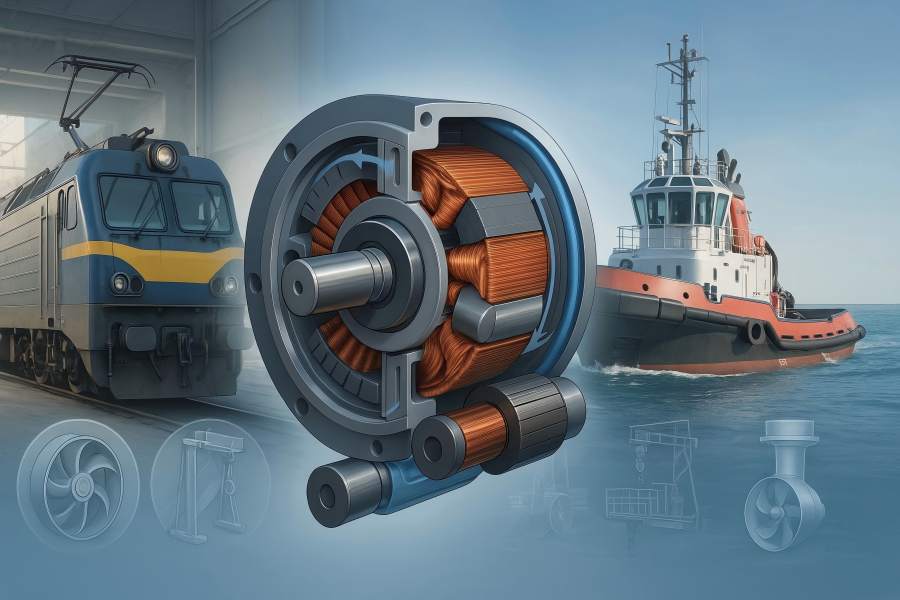
DC machines still excel on rails and at sea for their high starting torque, precise control, and durability. Optimizing the stator and rotor cuts losses and heat, boosts torque density, extends brush and bearing life, and delivers fewer overhauls, shorter downtime, smoother low-speed control, and real energy savings.
This article explains the key design choices for traction, auxiliaries, and marine propulsion.
Why stators and rotors dominate performance in DC machines
In any DC machine—series or shunt wound, compound, permanent-magnet DC (PMDC), or electronically commutated “DC” (BLDC)—the stator and rotor define the magnetic circuit and the copper pathway that produce torque and heat.
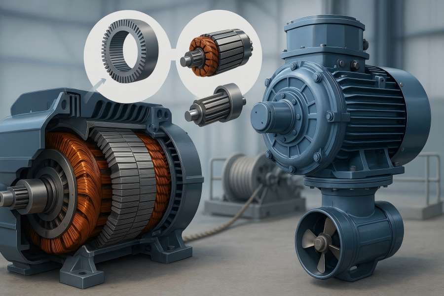
- Stator: Provides the main field. In wound-field DC machines, this means field poles and yoke; in PMDC/BLDC, it means permanent magnets or concentrated windings on the stator teeth. Flux density in the stator back-iron and pole faces drives core loss, saturation behavior, and torque capability.
- Rotor (armature): Hosts the armature windings and the commutator (or magnets in some topologies). Rotor geometry, slot shape, and commutator design govern current distribution, reactance, and commutation quality under load.
- Commutation: In brushed DC, mechanical commutation plus interpoles/compensating windings handle armature reaction. In BLDC, the power electronics execute commutation, but the same magnetic “plumbing” rules apply—steel grade, lamination thickness, slot/pole combination, skew, and end-winding length dominate losses and ripple.
Because iron and copper dominate losses (I²R, hysteresis, eddy) and air-gap physics sets force/torque, improvements in active parts pay off immediately in efficiency, heat, and torque smoothness—exactly the variables that matter in rail yards, tunnels, harbors, and open water.
Railway systems: traction and auxiliaries
Operating reality on rails
Rail traction demands brutal low-speed torque for train starts, grade climbs, and yard moves—often with long thermal soaks and shock/vibration from the track. Auxiliary systems (compressors, blowers, doors, fans, pumps) cycle constantly, where efficiency, acoustic noise, and easy maintenance matter.
What better stators and rotors do for traction
Higher starting torque and smoother creep
- Stator poles with optimized pole-shoe geometry and higher permeability back-iron reduce saturation at high field currents.
- Rotor slot geometry (semi-closed slots, optimized tooth tips) and correct commutator segment count keep reactance modest, avoiding sparking during heavy current commutation.
- Result: Higher torque at zero/low speed and less cogging/torque ripple for millimeter-accurate coupling and station creep.
Lower copper and iron loss → cooler operation
- Laminations at 0.27–0.35 mm in low-loss electrical steel cut eddy loss; moving from generic M270 to a modern high-silicon grade can trim core loss by 10–20% at the same flux.
- Winding fill factor improved from ~45% to ~55–60% with precise slot liners and rectangular conductors (or hairpin on BLDC), yielding lower DC resistance and 2–4% less I²R at operating current.
Better commutation under armature reaction
- Interpoles and compensating windings tuned to duty current minimize the transverse flux responsible for brush arcing and copper dust.
- Benefit: Brush life stretches (often 1.5–2×), commutator temperature falls 10–20 °C in like-for-like service.
Thermal headroom and survivability
- Insulation systems upgraded to Class F (155 °C) or H (180 °C) with vacuum-pressure impregnation (VPI) withstand heat soaks, inverter dv/dt (for chopper drives/BLDC), and contamination.
- Internal airflow or water-jacketed frames reduce hot-spot to average temperature spread; typical thermal rise reductions of 6–12 °C are achievable with the same frame.
Reliability in shock, dust, and moisture
- IP55–IP67 designs, sealed bearings, stainless hardware, and anti-tracking varnishes limit failure modes tied to brake dust, coal/iron ore fines, or tunnel humidity.
- Balancing to ISO 21940 G2.5 and skewed armatures reduces vibratory loads at commutation frequencies, lessening brush bounce and bearing wear.
What that means in numbers on a locomotive or EMU
Energy: 1.5–3.0% traction energy savings from active-part improvements alone (core + copper + smoother commutation), before any timetable or driver-assist optimizations.
Maintenance: Brush inspection/turn intervals extended from, say, 100–120 k run-km to 180–220 k run-km on comparable duty when armature reaction is tamed and temperatures drop.
Thermal: 8–12 °C lower steady-state hot-spot can push winding life by >2× on Arrhenius models.
Noise and ride: 1–2 dB(A) reduction at car floor for auxiliary drives from lower torque ripple and better balance.
Marine systems: propulsion, thrusters, and deck machinery
Marine duty is unforgiving
Salt fog, condensation, wide ambient swings, and shock loading from waves define the marine environment. Propulsion and dynamic positioning require precise low-speed torque, while winches, cranes, and windlasses face bidirectional peak loads, emergency braking, and frequent reversals.
How stator and rotor upgrades deliver at sea
Zero-speed torque and fine positioning
- Stator tooth/slot optimizations and intentional skew lower torque ripple, critical for tunnel and azimuth thrusters that must hold position against waves.
- PMDC/BLDC rotors with high-grade NdFeB and non-magnetic sleeves (Inconel, titanium, or carbon-fiber bands) resist burst forces and keep magnets secure at overspeed and cavitation transients.
Corrosion and moisture resilience
- Marine varnishes, anti-condensation heaters, desiccant-ready enclosures, and IP66–IP68 housings protect the active parts.
- Epoxy-glass slot liners and sealed end-windings prevent wicking and galvanic paths—failure rates drop sharply in tropical service.
Thermal management for continuous pulls
- Ducted stators with forced cooling drop core loss temperature rise; water-cooled frames unlock higher continuous ratings in the same footprint (often +10–15% continuous torque).
- Rotor ventilation paths or closed, jacket-cooled designs prevent commutator hot spots on long anchor-handling pulls.
Regenerative capability on winches
With compound or BLDC topologies, paying out line allows energy recovery to the DC bus/battery. The smoother armature reaction and lower losses from improved active parts turn more of that mechanical energy into usable electrical energy, not heat.
Classification compliance built into the metal
- Shock and vibration margins come from conservative flux densities, stiffer yokes, and shorter overhangs—not just paperwork.
- Insulation creepage/clearance and temperature rise governed by design yield clean type-test results with margin for surveyors.
Marine outcomes you can bank on
- Propulsion/thruster: ±1–2% thrust stability improvement at low RPM via ripple reduction; holding performance in DP improves without hunting.
- Winches/cranes: 5–10% higher continuous line pull in same frame when upgraded cooling and copper fill are combined; emergency stop temperatures remain within insulation class.
- Availability: Salt-fog-induced trips and earth faults fall markedly with sealed end-windings; auxiliary heaters cut morning condensation events.
Design levers in the stator and rotor that move the needle
- Electrical steel and lamination thickness: Choose low-loss grades with thickness 0.20–0.35 mm for traction/marine speeds. Thinner laminations reduce eddy currents; high-Si steel reduces hysteresis. Expect 8–20% core-loss cuts at working flux.
- Slot/pole and skew strategy: Semi-closed slots balance manufacturability with lower slot leakage; fractional slot/pole combinations and 1–1.5 slot pitch skew suppress torque ripple and acoustic noise.
- Winding architecture: Form-wound coils with precise packing and quality slot liners increase fill factor to ≥55%. Compensating windings embedded in the stator pole faces neutralize armature reaction near the commutator; this is the single most effective upgrade for heavy series-wound traction DC motors.
- Commutator and brushgear: More segments at larger diameter lower segment voltage and dθ/dt at the brush. Mica undercut depth and overlap geometry reduce high-speed sparking. Brush grade matched to current density and humidity avoids glazing; a better rotor reduces brush arcing, which further reduces commutator wear—a virtuous cycle.
- Magnets and sleeves (PMDC/BLDC): NdFeB with ∆T-stable grades (e.g., H/SH ratings) preserves flux at elevated temperatures. Nonmagnetic sleeves tame hoop stress and shield magnets from debris; carbon-fiber gives high strength with low eddy loss.
- Insulation system: Class F/H resin, corona-resistant films near slot openings, and robust end-winding bracing handle inverter pulses (even on “DC” BLDC) and shipboard voltage spikes. VPI ensures resin penetration and moisture resistance; test with partial discharge (even if DC) when PWM drives are used.
- Cooling: For traction: forced air through stator ducts, with fan curves matched to tunnel pressure drops. For marine: closed water jackets or external plate coolers; design for fouling factors typical in harbor water.
- Mechanical integrity and balance: Rotor overspeed to ≥120% rated, balance to ISO G2.5 or better, and stout end-ring/coil lashing stop migration in shock loads. Stainless or coated fasteners plus keyway/chock design maintain alignment through thermal cycles.
Quantified gains: example comparisons
The table below illustrates realistic, achievable deltas when only the stator and rotor are upgraded—same frame, same duty.
| Application & Duty Point | Baseline (Legacy) | Upgraded Active Parts | Improvement |
| Rail traction – 200 kW motor at 600 V, yard duty | Efficiency 91.0% | Efficiency 93.2% | +2.2 pp |
| Hot-spot rise 105 °C | Hot-spot rise 94 °C | −11 °C | |
| Brush life 110 k run-km | Brush life 200 k run-km | ~1.8× | |
| Torque ripple @ 5 km/h 4.0% p-p | 2.1% p-p | −48% | |
| Marine winch – 160 kW continuous pull | Efficiency 90.2% | Efficiency 92.0% | +1.8 pp |
| Continuous line pull 100% | 110% in same frame | +10% | |
| Commutator temp 115 °C | 98 °C | −17 °C | |
| Regen pay-out energy captured 70% | 80% | +10 pp | |
| Aux fan/blower – 30 kW | Sound pressure 82 dB(A) | 80 dB(A) | −2 dB |
| Mean time between brush service 8 k h | 14 k h | +75% |
Notes: Values represent mid-fleet outcomes when upgrading steel, winding fill, interpoles/compensation, and cooling; your exact gains depend on duty cycle and ambient.
Integration with modern DC power electronics
Even in “DC” fleets, power electronics sit between the source and the motor: choppers for traction, DC/DC converters in battery systems, and inverters for BLDC. Stator/rotor choices complement (or fight) those electronics.
- Field weakening for speed: Wound-field stators with robust thermal margins allow controlled field weakening for higher top speed without overheating.
- Regen stability: Smooth armature reaction and lower inductive spikes make brake choppers and battery charge controllers happier; less voltage chatter on the DC link.
- EMI management: Shorter end-windings and proper slot shielding cut loop area; combined with dv/dt filters, this reduces common-mode noise in car and ship systems.
Quality and testing
- Efficiency mapping across the duty matrix, not just a single point.
- Heat run to stabilized temperatures at maximum continuous current, with thermocouples on coils and commutator.
- Vibration and balance per ISO 21940 G2.5; spectrum shows commutation harmonics under control.
- High-potential and surge tests on windings; for PWM drives, verify partial discharge inception is comfortably above operating stress.
- Ingress protection (IP55–IP68 as specified) verified with dust/water tests; check heater function for condensation prevention.
- Marine classification witness tests for shock/vibration where applicable; confirm materials and creepage/clearance meet documentation.
Practical case
A. Heavy-haul diesel-electric locomotive (legacy DC traction motors)
Upgrading stator steel from generic to low-loss, increasing fill factor by ~8 pp, adding correctly sized interpoles, and re-machining the commutator lowered motor losses by ~2.4 pp at 20–40 km/h yard duty. Fleet data showed a 1.9% fuel reduction and brush life ~2×, with fewer flashovers under wet-rail starts.
B. Harbor tug winch motor
Replacing a tired wound-field DC motor with a BLDC inside the same frame (PM rotor, concentrated windings on the stator) and a sealed, water-cooled housing cut thermal rise by ~15 °C and boosted continuous line pull by 12%. Regen on pay-out stabilized and fed a DC-link battery buffer, reducing generator transients.
C. EMU auxiliary blower
A compound-wound DC motor received a stator re-stack and VPI re-insulation; rotor slots were re-profiled and skewed. Acoustic noise dropped 2 dB(A), efficiency rose from 89.6%→91.3%, and bearing temperature fell 6 °C.

