Linear Motor Stator
- Our linear motor stators deliver high thrust density, ultra-smooth force, tight tolerances, and dependable thermal behavior.
- We design, wind, and finish stator cores that drop into your magnet tracks and movers, powering precision semiconductor tools, battery lines, metrology, and automation.
- ±1 µm Repeatability with Linear Scale Feedback
- IP65 Sealed for Washdown Environments
- Core Options: Iron-core, Slotless Hybrid, Ironless
- Module width 30–250 mm; Height 15–120 mm
- Insulation Class F 155 °C or H 180 °C
Based on Geometry
Choose stator geometry tailored to your motion path, envelope, and environment to maximize force density, smoothness, and maintainability.
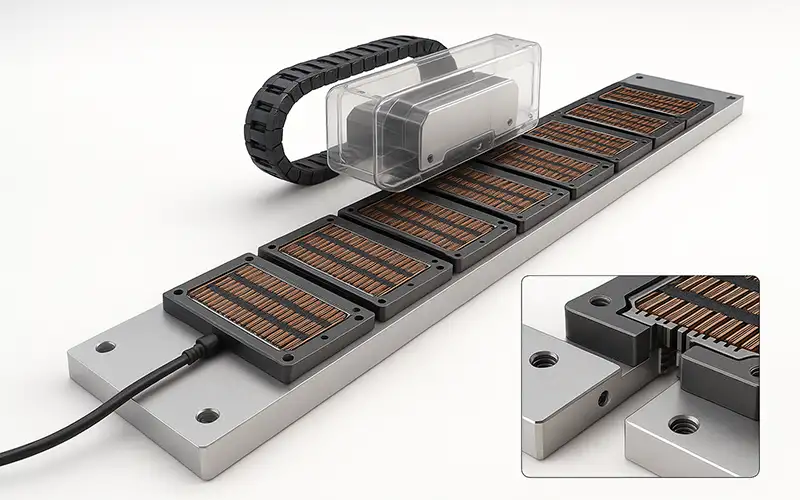
Flat / Planar (Track) Stators
- Rectangular stator modules for gantries, pick-and-place, laser/PCB processing, and metrology. Combine lengths to achieve long strokes.
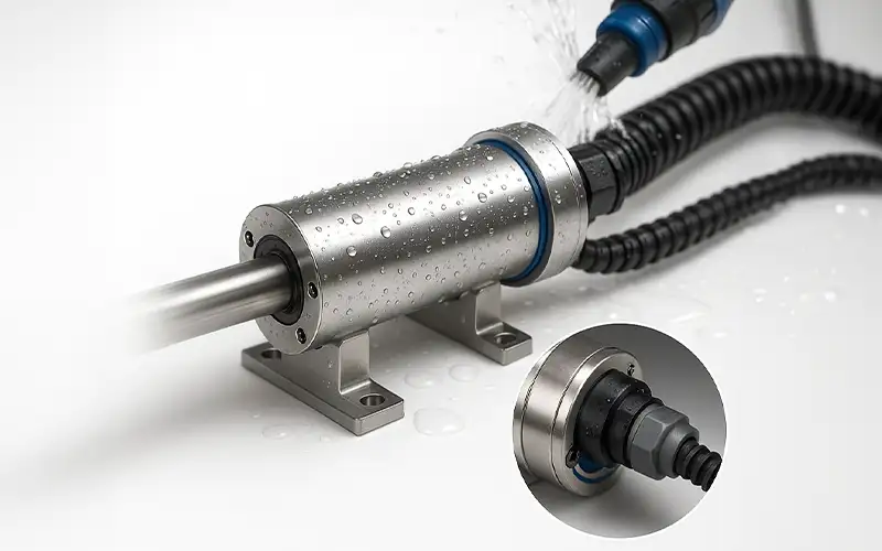
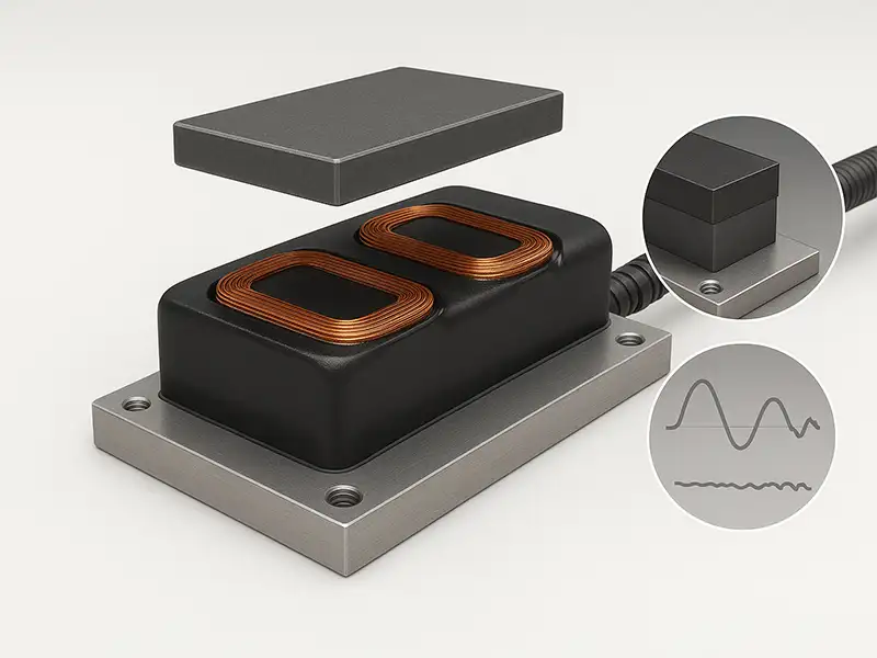
Tubular (Cylindrical) Stators
- Rod-type stators paired with a magnetized mover (or vice-versa). Compact footprint, sealed options, ideal for high acceleration and washdown.
Based on Core Topology
We provide iron-core, slotless hybrid, and ironless stators delivering high force, low cogging, and ultra-smooth motion for precision manufacturing applications.
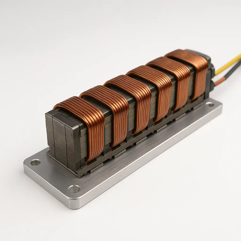
Iron-core (Slotted/Toothed)
- Coils wound around teeth on a laminated back-iron.
- Highest force density, good thermal path.
- Ideal for machine tools, press feeds and handling lines.
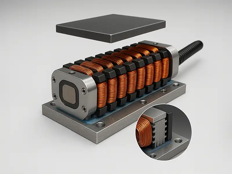
Slotless Iron-backed (Hybrid)
- Ironless coils over a smooth back-iron.
- Low cogging with improved force vs pure ironless.
- Suitable for precision stages needing smoother motion.
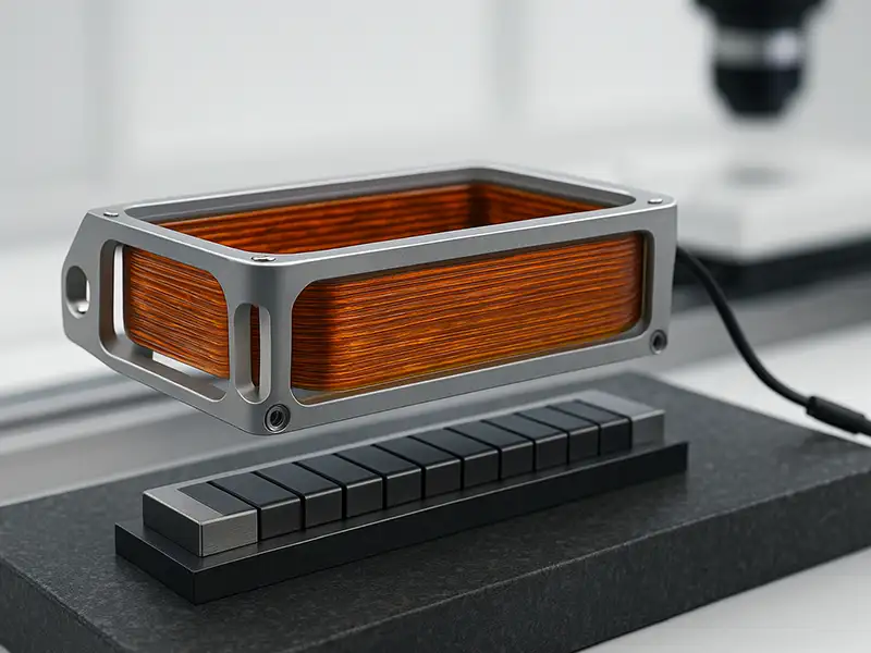
Ironless (Air-core)
- Zero cogging&attraction for ultra smooth motion.
- Lightweight coil enables acceleration & responsiveness.
- Ideal for semiconductor inspection metrology and scanning stages.
Typical Specifications
Typical ranges and options shown; we tailor stator dimensions, conductors, insulation, cooling, phasing, and tolerances to your track, duty, controller.
Parameter | Capability / Options |
Length (flat) | 50–2,000 mm single piece; longer via modular segments |
Width/Height (flat) | 30–250 mm / 15–120 mm typical |
Tubular Sizes | ID 16–80 mm, OD to 120 mm; stack length to 800 mm |
Laminations (iron-core) | 0.20 / 0.27 / 0.35 mm non-grain-oriented steel |
Conductors | Round, rectangular, or litz copper; AWG 16–30 equivalents |
Insulation Class | Class F (155 °C) or Class H (180 °C) |
Impregnation / Potting | VPI or epoxy potting; 0.8–2.0 W/m·K thermal fillers |
Cooling | Natural, forced-air, or liquid (manifolded channels) |
Phasing | 3-phase (standard); single/dual phases by request |
Sensors & Leads | PT100/PT1000/NTC thermal sensors; custom harnesses & connectors |
Geometry Control | Flatness ≤0.03 mm/100 mm; straightness ≤0.05 mm/m (typical build targets) |
Electrical Tolerances | Resistance ±5%, inductance ±7% (per drawing) |
Finish | Anodized/painted housings; anti-corrosion coatings on steel |
Key Advantages
Frictionless, Quiet Operation
Non-contact moving parts eliminate wear, noise, and particles; ideal for labs and medical settings.
Precision Motion Control
Maintains constant speed with high resolution for micro-positioning and accurate dispensing.
Wide Speed Envelope
From ultra-slow 8 μm/s to >10 m/s for both delicate tools and high-speed printers.
Long-stroke, Harsh-environment Ready
Up to 4.6 m travel; reliable in vacuum and in oil/water production areas.
Our Manufacturing Process
- We ensure every linear motor stator meets the highest standards through precision engineering and strict quality control.
- Mold Design & Engineering: Develop precision stamping die designs based on prototype results and required stator tolerances.
- Lamination Stamping: Punch high-precision silicon steel laminations for optimal electromagnetic performance.
- Stacking and Bonding: Align and bond laminations to form a solid stator core.
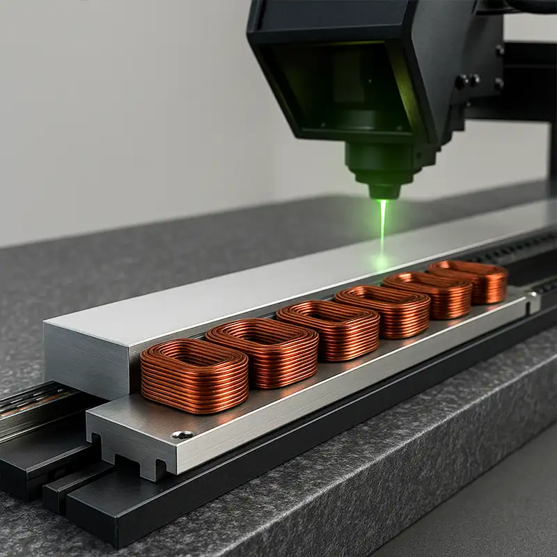
- Coil Winding: Wind copper coils accurately to ensure consistent current distribution and efficiency.
- Insulation Treatment: Apply heat-resistant coatings to enhance electrical safety and durability.
- Impregnation and Curing: Vacuum impregnate resin to strengthen coil bonding and thermal stability.
- Machining and Finishing: Precisely machine surfaces to meet dimensional and tolerance specifications.
- Testing and Quality Assurance: Conduct electrical, mechanical, and thermal tests for performance verification.
- Final Inspection and Packaging: Inspect visually and package stators for safe, clean delivery to clients.
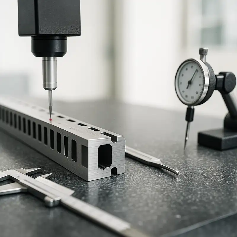
Quality & Testing
- Every linear motor stator undergoes dimensional, core integrity, electrical, and thermal validation with traceable documentation, meeting specified control plans and reporting requirements.
- Dimensional Control: Slot and pole pitch, tooth profile, straightness, flatness, and stack alignment are verified.
- Core Integrity: Lamination count and stacking factor are confirmed, welds or bonds inspected, and burr height controlled.
- Electrical Tests (wound units): Resistance, inductance, hi-pot, and surge are performed with full coil-set traceability.
- Thermal Validation: ΔT versus current curves established, thermistor calibration verified, and optional heat-run reports provided.
- Documentation: Control plans, inspection records, required serialization, and customer-specified reporting are maintained and delivered.
Customer Case
- Laser micromachining stage OEM for North American medical-device fabs needing 15% higher continuous force in the same footprint, lower force ripple for cleaner cuts, and reduced thermal rise to protect optics.
Our Solution
- Slotless iron-backed stators with optimized toothless windings, 0.27 mm back-iron laminations, ±3% phase-inductance matching, embedded PT1000 sensors, and a ground mounting face ≤0.02 mm per 300 mm, delivered as 600 mm tileable segments for the existing magnet tracks.
Results
Metric | Before | After |
Continuous force @ 10 A (per mover span) | 120 N | 145 N |
Peak-to-peak force ripple | 3.5% | 1.2% |
Thermal rise @ 10 A (steady-state) | 42 °C | 36 °C |
Mounting-face flatness (over 300 mm) | 0.04 mm | 0.02 mm |
Stage straightness over 500 mm (system) | 8 µm | 5 µm |
Production first-pass yield (first 5k pcs) | 97.2% | 99.0% |
General FAQs
What materials do you use for linear motor stator laminations and why?
Electrical steel laminations, grain-oriented or non-oriented, with controlled thickness reduce core losses, limit eddy currents, and deliver reliable magnetic performance. under load.
What insulation systems are applied in linear motor stator manufacturing for reliability?
Class F or H insulation uses enamelled wire, slot liners, wedges, and vacuum-pressure impregnation, resisting partial discharge, vibration, ingress, and thermal cycling.
What tests verify phase resistance and inductance on a finished linear motor stator?
Four-wire Kelvin resistance and LCR inductance at specified frequencies verify phases; defined imbalance limits and matching targets support accurate control and performance.
What back-iron options exist for a linear motor stator, and when to choose each?
Iron-core maximizes force density and heat removal; slotless iron-backed improves smoothness; ironless eliminates attraction, enabling fastest acceleration for delicate payloads and metrology.
How is cleanliness controlled during linear motor stator assembly to avoid contamination?
Clean zones, sealed packaging stages, lint-free handling, and non-silicone chemistries protect bond surfaces, prevent inclusions, and preserve insulation resistance for sensitive assemblies.
What surface treatments are used on linear motor stator cores for corrosion protection?
Phosphate, e-coat, or nickel plating resist corrosion; chosen finishes preserve magnetic properties and maintain contact resistance at mounting interfaces during service life.
What packaging ensures a linear motor stator arrives damage-free and inspection-ready?
Foam corner protection, VCI wraps, desiccants, and rigid crates secure components; shock and tilt indicators and documentation pouches ensure damage-free, inspection-ready deliveries.

