Induction motors power many industrial systems like fans, elevators, and conveyors. The stator and rotor must meet strict dimensional tolerances to work properly. Even small errors can cause energy loss, noise, vibration, or failure.
Fundamentals of Induction Motor Design
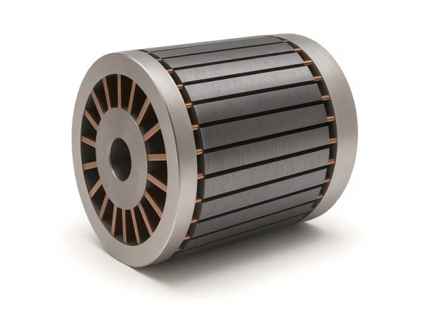
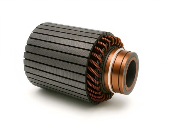
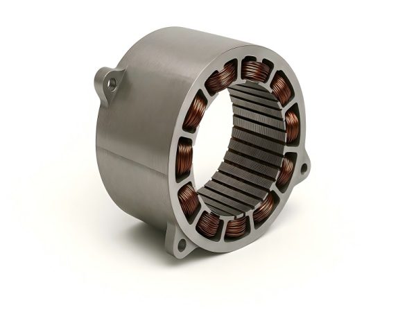
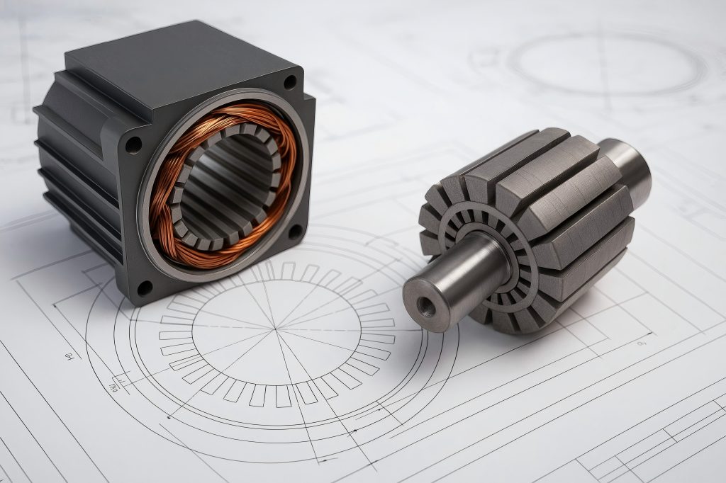
Stator and Rotor: Structural Overview
The induction motor’s stator is its stationary component. It has slots where windings are inserted, and when powered, it produces a spinning magnetic field. The rotor is the rotating element located inside the stator’s bore, and it typically consists of laminated steel cores and conductors forming a squirrel cage or wound rotor.
Motion results from the exact interplay between the induced current in the rotor and the magnetic field of the stator. However, this interaction depends heavily on air gap uniformity, geometric alignment, and overall mechanical fit—all of which are controlled by tolerance values.
Air Gap and Its Role
The tiny space between the rotor’s outer diameter and the stator’s inner diameter is known as the air gap. Too large an air gap reduces magnetic flux density and efficiency; too small, and there’s a risk of physical contact during operation due to thermal expansion or dynamic runout.
The typical air gap in an industrial motor might range from 0.2 mm to 2 mm, depending on the size and rating. This seemingly small space is one of the most sensitive tolerance-controlled dimensions in the motor.

Types of Tolerances in Stator and Rotor Design
Dimensional Tolerances
Dimensional tolerances refer to allowable deviations in physical measurements, such as diameters, lengths, and slot dimensions. Examples include:
- Rotor outer diameter (OD)
- Stator inner diameter (ID)
- Shaft diameters and fits
- Slot width, depth, and pitch
These tolerances influence both assembly compatibility and performance. Common standards like ISO 286-1 or ANSI B4.1 help define standard fits and clearances.
Geometric Tolerances
Geometric tolerances deal with form and positional attributes, including:
- Concentricity between rotor and shaft
- Circular runout of rotor laminations
- Parallelism of stator core faces
- Flatness and squareness of core assemblies
Geometric deviations affect balance, vibration, and magnetic symmetry. They must be strictly controlled, especially in high-speed or precision applications.
Magnetic Tolerances
Magnetic tolerances refer to variations in the magnetic circuit due to inconsistencies in:
- Core stacking
- Lamination orientation
- Slot insulation thickness
- Air gap uniformity
While not typically documented in the same way as mechanical tolerances, they are equally critical to performance.
International Standards and Tolerance Classifications
ISO and IEC Standards
Engineers rely on globally accepted standards to guide stator and rotor manufacturing tolerances. These include:
- ISO 286-1: Establishes tolerances and dimensions for cylindrical components.
- ISO 1940-1: Balancing quality requirements.
- IEC 60034-1: Rotating electrical machines—performance and testing.
- IEC 60072: Dimensions and output ratings of electrical machines.
Each of these provides guidelines for tolerances on size, concentricity, shaft fits, and other key features.
Tolerance Classes
Frequently, “IT grades” (International Tolerance grades) are used to specify tolerances. For example:
- IT6: High precision (used for shaft bearings)
- IT7–IT8: Typical for rotor/stator fits
- IT9–IT10: Acceptable for laminated stack dimensions
The lower the IT grade number, the tighter the tolerance.
Critical Tolerances in Stator and Rotor Components
Stator Bore Tolerance
The stator bore must maintain concentricity and roundness, as any deviation affects air gap consistency. Typical tolerance: ±0.02–0.1 mm, depending on motor size.
Rotor Outer Diameter Tolerance
The rotor OD must be tightly controlled to match the stator bore while preserving the required air gap. Tolerance range: ±0.01–0.05 mm.
Shaft and Bearing Fits
The rotor shaft must fit precisely with bearings and couplings. Tolerances depend on the fit type:
- Interference fits: Tight tolerance (e.g., H7/k6)
- Clearance fits: Slight play allowed (e.g., H7/g6)
Slot and Tooth Tolerances
Slot width, depth, and spacing influence winding insertion, magnetic symmetry, and eddy current losses. Misalignment or excessive deviation can lead to noise or hot spots.
Measuring and Verifying Stator and Rotor Tolerances
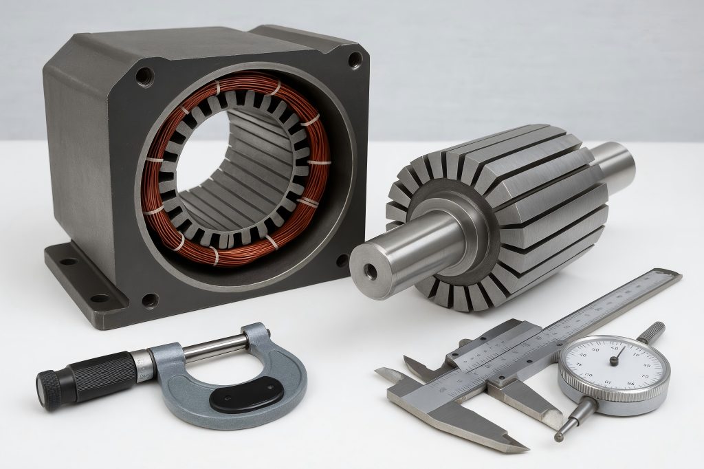
Metrology Tools and Techniques
Accurate measurement is the cornerstone of tolerance control in motor manufacturing. Engineers use both contact and non-contact tools, depending on the required resolution and surface geometry:
- Micrometers and Calipers: Common for shaft diameter, lamination stack length, and slot width.
- Coordinate Measuring Machines (CMMs): These devices measure shape, orientation, and position in three dimensions; they are perfect for flatness and concentricity.
- Laser Scanners and Optical Probes: Suitable for high-speed, non-contact dimensional verification of stator bores and rotor profiles.
- Dial Indicators: Used to measure runout on shafts and rotor assemblies.
Tolerance Stack-Up Analysis
Even when individual parts meet their specified tolerances, cumulative errors (stack-up) can result in assembly misfits or excessive vibration. Tolerance stack-up analysis—often conducted with statistical or worst-case methods—helps engineers assess the overall dimensional variability across mating components.
Online vs. Offline Inspection
Offline inspection is suitable for batch verification during or after production.
In-line (on-machine) inspection uses sensors, cameras, or probes during the machining process to detect deviations in real time, enabling immediate corrective action.
Manufacturing Challenges in Achieving Tight Tolerances
Lamination Punching and Stacking
Progressive dies are used to punch laminations for the stator and rotor from electrical steel sheets. Issues include:
- Die wear: Affects dimensional precision and edge quality.
- Burr formation: Impacts stack height and electrical performance.
- Misalignment: Causes concentricity issues when stacking.
Solutions include carbide tooling, laser cutting for prototypes, and automated stacking with vision alignment systems.
Heat-Induced Distortion
Heat from welding, shrink fitting, or annealing can cause:
- Shaft bending
- Lamination warping
- Bore distortion
Controlled heat-treatment cycles and stress-relief techniques are used to minimize thermal distortion.
Shaft Pressing and Balancing
Rotor shafts are press-fit or shrink-fit into the core, requiring precise interference values. Any misalignment can cause imbalance or bearing failure. Dynamic balancing (per ISO 1940) is performed after assembly to correct residual eccentricities.
Tolerance’s Effect on Mechanical and Magnetic Performance
Magnetic Performance
Tolerances directly influence the motor’s electromagnetic behavior:
Uneven air gap → Unbalanced magnetic pull → Noise, vibration, and reduced efficiency.
Slot mismatch → Asymmetric magnetic flux → Increased core losses and heating.
Mechanical Integrity
Poor tolerance control may result in:
- Bearing wear due to shaft misalignment
- Vibration-induced fatigue
- Shaft deflection or bending
These issues shorten motor lifespan and increase maintenance costs.
The Role of Thermal Expansion in Tolerance Design
Thermal Effects on Rotor-Stator Clearance
During operation, components expand due to heat. Engineers must anticipate:
- Stator bore expansion (moderate)
- Rotor shaft expansion (greater due to higher thermal mass and frictional heating)
This thermal mismatch may narrow the air gap or create interference. Engineers use coefficients of thermal expansion (CTEs) and thermal simulation to adjust cold-state tolerances.
Material Pairing Strategies
Matching materials with similar thermal expansion rates—such as using the same grade of electrical steel and shaft steel—helps maintain tolerance stability under load.
Lifecycle Tolerance Considerations
Wear and Deformation Over Time
Tolerances shift due to:
- Bearing wear
- Core loosening
- Cyclic thermal loading
- Environmental corrosion
Designers must factor in tolerance drift over the motor’s operational lifespan and specify appropriate clearances or use self-lubricating/balancing features.
Maintenance and Reassembly Tolerances
During motor servicing, components are disassembled and reassembled. Interference fits may loosen, and dimensions may change. Engineering drawings often include serviceable limits—acceptable tolerance ranges after repeated cycles.
Case Study 1: Air Gap Deviation and Vibration in HVAC Motors
An HVAC manufacturer observed excessive vibration and noise in their blower motors. Investigations revealed non-uniform air gaps caused by rotor shaft misalignment and out-of-tolerance stator bore diameters.
Root Cause
- Misaligned stator stack during assembly
- Rotor shaft tolerance outside of IT7 standard
Resolution
- Updated the assembly process to include concentric alignment pins
- Switched to CNC-machined rotor shafts with in-process metrology checks
- Achieved air gap uniformity within ±0.05 mm
Outcome
- Vibration reduced by 40%
- Power efficiency increased by 3%
- Warranty claims decreased by 18%
Case Study 2: Rotor Concentricity Issues in Industrial Pumps
A water pump manufacturer faced premature bearing failure in large induction motors used in municipal pumping stations.
Analysis
- CMM inspections revealed rotor OD eccentricity of 0.12 mm (spec: ≤0.05 mm)
- Poor fixture stability during shaft insertion was identified as the culprit
Action Taken
- Re-designed the rotor press-fit process with hydraulic alignment
- Implemented concentricity check with dial gauges during assembly
Result
- Rotor runout reduced from 0.12 mm to <0.03 mm
- Bearing life extended by 60%
- Motor failure rate dropped significantly in field installations
Simulation and Digital Twin Approaches to Tolerance Management
Finite Element Analysis (FEA)
Modern design practices use FEA to simulate:
- Magnetic field interaction with varying air gaps
- Thermal expansion and its effect on fit
- Structural response under centrifugal forces
FEA helps optimize tolerances before physical prototyping.
Digital Twin Modeling
Digital twins create virtual replicas of motors that mirror real-world tolerance shifts during operation. By combining IoT sensors with CAD/CAM data, engineers can:
- Predict component degradation
- Simulate tolerance drift scenarios
- Optimize maintenance schedules
Tolerance Optimization for Specific Applications
High-Speed Motors
- Motors operating above 10,000 RPM require:
- Tighter rotor concentricity (≤0.02 mm)
- Balanced laminations
- Symmetrical shaft fits
Any tolerance deviation can induce destructive harmonics and mechanical failure.
Submersible Motors
- Exposure to moisture and pressure affects tolerance requirements:
- Shafts need corrosion-resistant coatings with tight clearance
- Tolerances for seals must account for swelling and contraction
Energy-Efficient Motors (IE3/IE4)
To reduce losses:
- Rotor-stator alignment must be near-perfect
- Core lamination stacks must maintain flatness and tight height tolerances
Best Practices and Recommendations for Engineers
Early Tolerance Analysis
Involve tolerance simulation during the CAD design phase to anticipate and resolve potential conflicts. Use worst-case and statistical tolerance stack-ups.
Supplier and Vendor Alignment
Share engineering drawings with exact tolerance specs. Request SPC (statistical process control) data from suppliers to monitor critical dimensions.
Design for Manufacturability (DFM)
Avoid unnecessarily tight tolerances that increase cost without functional benefit. Balance performance with practical machinability and assembly feasibility.
Continuous Training
Regular training for operators and quality personnel on measuring tools, reading GD&T (Geometric Dimensioning & Tolerancing), and interpreting motor drawings is essential for consistent quality.

