Electric motors power everything from robots and vehicles to home appliances. At their core are two key parts: the rotor and stator. These components directly affect motor performance, efficiency, and how well a motor suits specific applications. Knowing the difference between them helps engineers and developers make smarter design choices and solve problems more effectively.
What Is Motor Rotor?
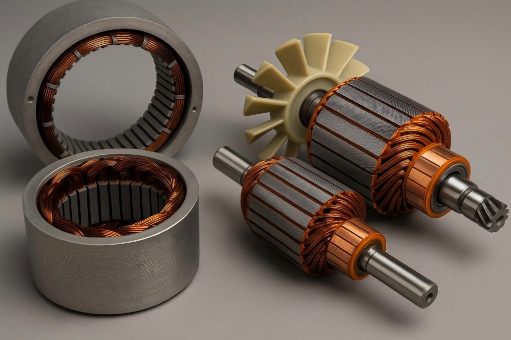
An electric motor’s rotor is its revolving component. It is attached to the motor shaft and is the component that delivers mechanical power to external systems. The rotor rotates when it is powered by magnetic interaction with the stator, creating rotational motion.
Rotors can be classified into several types depending on motor design:
- Squirrel Cage Rotors: Common in AC induction motors; shaped like a hamster wheel and made of laminated iron cores with conductive bars.
- Wound Rotors: Used in slip-ring motors; include windings connected to external resistors for torque control.
- Permanent Magnet Rotors: Found in brushless DC motors (BLDC) and synchronous motors; use magnets mounted on or embedded in the rotor.
- Salient Pole Rotors: These are frequently seen in synchronous machines and have projecting poles.
Regardless of type, the rotor’s core function is to convert electromagnetic energy into mechanical torque, making it the actionable element of the motor’s design.
What Is Motor Stator?
The stator is the stationary part of the motor and is responsible for producing a rotating magnetic field. It surrounds the rotor and typically contains a laminated iron core wound with copper or aluminum wire coils. These windings carry current and create the magnetic field that interacts with the rotor.
Stator designs vary by motor type:
- Slotted Core Stators: Windings are placed inside the slots of the laminated core.
- Coreless Stators: Have no iron core; the windings are self-supporting, reducing eddy current loss.
- Segmented Stators: Made of multiple modular pieces to ease assembly and cooling.
The stator essentially serves as the electromagnetic engine of the motor, inducing field forces that ultimately generate motion in the rotor.
Core Functional Difference Between Rotor and Stator
| Component | Function | Movement | Energy Role |
| Rotor | Converts electromagnetic energy into mechanical rotation | Rotating | Receives magnetic force |
| Stator | Generates electromagnetic field through windings | Stationary | Creates magnetic field |
At the core, the stator is the source, and the rotor is the receiver. The stator establishes the electromagnetic conditions necessary for operation, while the rotor responds by rotating in reaction to these fields. In short, the stator drives, and the rotor performs.
How the Rotor and Stator Work Together to Generate Motion
The motor’s capacity to generate torque is determined by the interaction between the stator and rotor. A rotating magnetic field is produced when alternating current passes through the stator windings.
This field cuts across the air gap between the stator and rotor, inducing an electromotive force (EMF) in the rotor. This EMF triggers the rotor to produce its own magnetic field and start revolving in accordance with Lenz’s Law and Faraday’s Law of Electromagnetic Induction.
In synchronous motors, the rotor and rotating field lock in at the same speed. Slip, a prerequisite for inducing current, is created in induction motors when the rotor lags slightly behind the stator field.
The balance and precision of this electromagnetic interaction are vital. Misalignment or inefficiencies in the air gap, stator winding configuration, or rotor shape can degrade performance significantly.
Physical Placement and Structural Contrast
Physically, the rotor and stator are arranged concentrically. The stator is fixed around the perimeter, mounted to the housing. The rotor sits inside the stator and is directly attached to the motor shaft.
Table: Physical Comparison
| Feature | Rotor | Stator |
| Location | Inside | Outside |
| Movement | Rotates with shaft | Fixed to housing |
| Core Design | Shaft, iron core, conductor bars or magnets | Laminated core with windings |
| Cooling Methods | Shaft-mounted fan, internal airflow | Housing fins, external fans, water jackets |
This structure ensures optimal magnetic coupling while maintaining mechanical clearance for smooth rotation.
Magnetic Field Interaction
One of the most essential differences between the rotor and stator is their roles in magnetic interaction:
- The stator induces a magnetic field.
- The rotor reacts to the induced field, generating motion.
In brushed DC motors, the rotor contains the windings, and a commutator switches current direction. In contrast, BLDC and AC motors usually place the windings in the stator and magnets or conductive bars in the rotor. This arrangement simplifies heat dissipation and reduces wear from moving electrical contacts.
The type and frequency of current applied to the stator influence the resulting magnetic field, which in turn controls rotor speed and torque.
Energy Flow
Energy flow in an electric motor follows a clear path:
- Electric Power Input – Supplied to the stator.
- Magnetic Field Generation – Current through the windings induces a rotating magnetic field.
- Induced Rotor Current or Magnetic Coupling – Rotor either generates current (induction) or aligns with field (synchronous).
- Mechanical Rotation – Rotor converts magnetic interaction into torque.
- Output Work – Delivered through the rotor shaft to drive external loads.
This energy transformation from electrical to magnetic to mechanical is highly efficient, particularly when rotor-stator interaction is optimized with minimal air gap and precision winding.
Material and Design Differences in Rotor vs. Stator
| Feature | Rotor | Stator |
| Core Material | Laminated silicon steel, aluminum, copper | Laminated silicon steel |
| Windings | In wound rotors (or none in squirrel cage) | Copper or aluminum |
| Additional Elements | Permanent magnets, slip rings | Iron laminations, insulation |
| Structural Constraints | Must withstand centrifugal forces | Must dissipate heat efficiently |
Design considerations for rotors prioritize inertia control, balance, and magnetic alignment. Stators, meanwhile, are engineered for electromagnetic performance, thermal conductivity, and winding durability.
Advanced motors now use laser-cut lamination stacks, high-efficiency magnet arrangements (like Halbach arrays), and vacuum impregnation to enhance both rotor and stator integrity.
Rotor and Stator in AC vs. DC Motors
| Motor Type | Rotor Features | Stator Features |
| AC Induction | Squirrel cage or wound | Energized by AC to produce rotating field |
| AC Synchronous | Permanent magnet or salient pole | Excited to rotate synchronously with rotor |
| Brushed DC | Wound with commutator | Permanent magnets or wound coils |
| BLDC | Permanent magnets | Electronic commutation with wound coils |
In AC motors, the stator generates a rotating field via alternating current. In DC motors, mechanical or electronic commutation is used to achieve the same effect. The rotor-stator roles reverse in some cases, especially in older DC motor designs.
Brushless vs. Brushed
In brushed motors:
- Rotor carries windings, and brushes supply power via commutators.
- The stator has permanent magnets or field windings.
In brushless motors:
- Stator carries the windings.
- Rotor contains permanent magnets.
- Commutation is handled electronically, not mechanically.
This switch leads to:
- Higher durability (no brush wear)
- Better thermal efficiency (stationary windings dissipate heat better)
- Quieter operation and more precise control
Hence, brushless motors dominate in high-performance applications like drones, robotics, and electric vehicles.
Thermal Management and Efficiency Considerations
The stator generates the majority of heat in most motors due to winding resistance. Efficient thermal management is critical to maintaining long-term motor performance.
| Component | Heat Generation | Cooling Methods |
| Stator | High (from windings) | Fans, heat sinks, water cooling |
| Rotor | Moderate (from eddy currents or windings) | Shaft fans, thermal paths |
Designing motors with efficient stator cooling—via forced-air or liquid systems—can drastically improve performance. Rotor designs also aim to reduce losses from eddy currents by using laminated steel and avoiding excessive magnetic saturation.
Real-World Applications
Choosing the right motor involves understanding rotor-stator configurations:
- BLDC Motors (Stator windings, rotor magnets): Ideal for drones, HVAC, EVs.
- Induction Motors (Stator coils, squirrel cage rotor): Suitable for fans, pumps, and industrial conveyors.
- Stepper Motors (Segmented rotors and stators): Used in CNC machines and 3D printers.
- Synchronous Motors (Rotor matches stator frequency): Great for precision automation.
Your choice depends on torque needs, speed control, load type, and efficiency requirements. A mismatch can result in overheating, vibration, or premature failure.

