In electric motor design, one of the most overlooked but critically important elements is the number of slots in the stator and rotor. These slots are not just structural features; they profoundly influence the motor’s torque, vibration, thermal behavior, and efficiency. Asynchronous motors—widely used in industrial and commercial applications—are especially sensitive to this design aspect.
Understanding Slot Functions
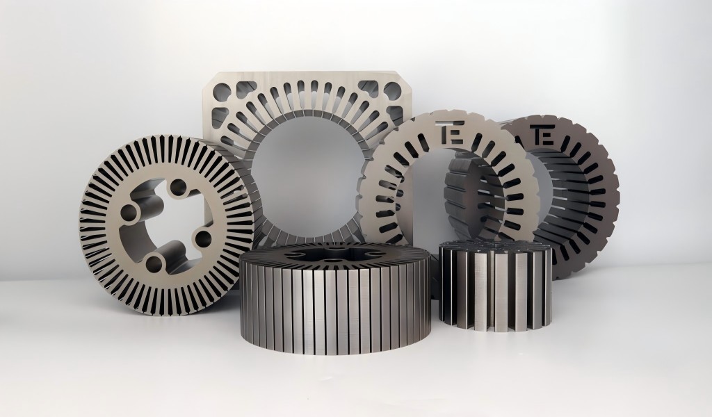
In an asynchronous motor, the stator and rotor work together to generate rotational force through electromagnetic induction. The motor’s rotor revolves inside the stator, which is the exterior, immovable component. Both components include regularly spaced slots, which serve the following roles:
- Stator slots house copper windings that, when energized by alternating current, produce a rotating magnetic field.
- Rotor slots (typically filled with conductive bars in squirrel-cage motors) generate current through electromagnetic induction when exposed to the rotating stator field.
This interaction results in a torque-producing force that drives the rotor. The number of slots, their shape, and how they’re distributed significantly impact how well this electromagnetic interaction occurs.
More slots can allow better magnetic field shaping and increased conductor fill, but they can also complicate manufacturing, increase cost, and weaken structural components. Fewer slots simplify construction but may reduce performance in critical areas.
Magnetic Field and Harmonic Impact
The rotating magnetic field in an asynchronous motor should ideally be smooth and sinusoidal. However, due to the discrete nature of slotting, the field contains space harmonics—additional waves that distort the main magnetic waveform.
Poorly selected slot combinations (e.g., equal or closely matched stator and rotor slots) can cause the following problems:
- Magnetic locking, where the rotor attempts to align with certain stator teeth repeatedly, leading to pulsating torque.
- Increased noise and vibration, especially under load changes.
- Greater iron and copper losses reduce the motor’s overall efficiency.
To mitigate these effects, engineers prefer non-integer slot combinations. For example, a stator with 36 slots might be paired with a rotor having 28, 29, or 31 slots. This asymmetry breaks the periodic harmonic interaction and improves flux distribution in the air gap.
These electromagnetic interactions are frequently simulated and visualized in motor design using Finite Element Analysis (FEA). It allows optimization of slot numbers before physical prototypes are produced.
Cogging Torque and Noise
Cogging torque is a specific form of torque ripple caused by the tendency of rotor teeth to align with stator slots when no current is applied. This effect becomes problematic in applications requiring smooth motion, such as elevators, CNC machines, and robotics.
The magnitude of cogging torque is directly related to:
- The number of slots and whether the stator and rotor counts share common multiples.
- The slot pitch, or spacing between adjacent slots.
- The magnetic material properties of the stator and rotor cores.
Design techniques to reduce cogging torque include:
- Choosing stator and rotor slot numbers without shared factors.
- Skewing the rotor bars slightly along the axial direction averages the cogging forces over the rotor’s length.
- Using fractional-slot windings, which distribute the magnetic forces more uniformly.
By minimizing cogging torque, motor designers can reduce vibration, noise, and bearing wear, improving the overall quality and lifespan of the machine.

Rotor Slot Count and Starting Characteristics
Slot numbers also influence the motor’s behavior during startup—a critical performance stage for asynchronous motors.
- A higher number of rotor slots reduces leakage reactance and increases resistance during startup, lowering the inrush current but potentially reducing torque.
- Fewer rotor slots offer higher starting torque, which may be useful in applications with high initial loads, but also result in higher current draw.
To balance these competing needs, some designs use:
- Deep-bar rotors, which provide higher resistance at startup and lower resistance during normal operation due to the skin effect.
- Double-cage rotors, which feature two sets of rotor bars with different resistance and reactance characteristics to optimize both startup and running performance.
In motors connected directly to the power grid (direct-on-line starters), rotor slot design is particularly important for managing electrical stress and ensuring smooth acceleration. In inverter-driven systems, slot optimization can complement electronic control strategies to enhance efficiency and torque control.
Thermal and Efficiency Considerations
Slot number and shape affect not just the electromagnetic performance but also heat generation and dissipation in the motor.
Key thermal impacts include:
- Copper losses (I²R losses) are influenced by how densely the windings can be packed into the stator slots.
- Core losses, including hysteresis and eddy current losses, which depend on the magnetic field’s waveform shape—again, influenced by slot number.
- Cooling effectiveness, since rotor slots act as heat conduits. Their shape and depth affect how quickly heat can be transferred to the outer surface and eventually dissipated.
Designers must carefully balance slot fill factor (how much copper is used) with available core area (to prevent magnetic saturation). Using too many slots reduces tooth width, which increases magnetic flux density and the likelihood of core heating.
Thermal simulation software, often coupled with electromagnetic modeling, helps identify hot spots and evaluate whether the slot configuration provides adequate cooling for the intended application.
Mechanical and Structural Aspects
Mechanically, slot configuration can impact the structural integrity of the stator and rotor.
- Too many slots result in thinner teeth between them, reducing the component’s ability to withstand mechanical stress, especially under high rotational speeds or load shocks.
- Narrow gaps have the tendency to concentrate mechanical stress, which over time may cause fatigue or breaking.
- Skewed slots, while electromagnetically advantageous, can reduce the rotor’s torsional rigidity, requiring stronger materials or design compensations.
In motors designed for high-speed operation, such as 2-pole designs operating at 3000 RPM (50 Hz), these factors become particularly critical. Here, the motor must withstand centrifugal forces without deformation or imbalance.
As a rule of thumb, high-speed motors are designed with a moderate number of slots and reinforced materials, balancing electromagnetic benefits with structural reliability.
Best Practices and Slot Combinations
Certain combinations of stator and rotor slots have become industry standards for specific applications, balancing efficiency, smooth torque, manufacturability, and cost.
| Stator Slots | Rotor Slots | Application |
| 36 | 28, 29 | General-purpose industrial motors |
| 48 | 37, 38 | High-efficiency or inverter-fed motors |
| 72 | 56, 58 | Large fans, compressors, and heavy-duty drives |
| 24 | 20, 22 | Small fractional horsepower motors |
Design guidelines:
- Avoid stator and rotor slot numbers that share a GCD > 1.
- Apply skewing of one stator slot pitch where feasible.
- For performance verification, use heat analysis and FEA early in the design phase.
These combinations help minimize torque ripple, acoustic noise, and manufacturing complexity while delivering robust performance across a range of operating conditions.
Case Study Example
A pump manufacturer was experiencing elevated noise and reduced reliability with their 15 kW asynchronous motor design. Originally, both stator and rotor were built with 36 slots. During startup, vibration levels were high, and users reported early bearing failure.
After simulation and analysis, the rotor slot count was changed from 36 to 29, and the rotor bars were skewed by one slot pitch.
Results:
- Noise levels dropped by 7 dB.
- Starting torque increased by 15%.
- Service life (based on accelerated aging tests) improved by 22%.
- Customer complaints were reduced by 80% within the first year of the redesign.
This example shows how even little changes to slot numbers can result in quantifiable gains in performance in the real world.

